AAAANNNDDD.... (Drum roll please)... I got it working for 6 LEDs.
There are a few problems though.The code works fine, but regardless, here it is for anybody who wants it.
void setup_pwm()
{
 DDRB|=(1<<PORTB1);  //Define port B1 as output
 DDRB|=(1<<PORTB2); //Define port B2 as output
 DDRB|=(1<<PORTB3);
 TCCR1A=0xA1;        //Set B1 as PWM and set 2 of 4 registers for PWM type
 TCCR1B=0x01;     //Set 2 of 4 registers for PWM type and 3 registers for prescaler
 TCCR2=0x61;
 OCR1A = 0;
 OCR1B = 0;
 OCR2 = 0;
}


int globdim;

int main()
{
 unsigned int ct=1;
 setup_pwm();

 for(ct=1;ct<2000;ct++)
 {
  if (ct<=201)
  {
   if (ct == 1)
    DDRD|=(1<<PORTD0);  //LED1 On
   OCR1A++;    //LED1 brightness up
  }
  else if ((ct>201) && (ct<=402))
  {
   if (ct == 402)
    DDRD&=~0x01;  //LED1 Off
   OCR1A--;    //LED1 brightness down
  }


  if ((ct>134) && (ct<=335))
  {
   if (ct == 135)
    DDRD|=(1<<PORTD1);  //LED2 On
   OCR1B++;    //LED2 brightness up
  }
  else if ((ct>335) && (ct<=536))
  {
   if (ct == 536)
    DDRD&=~0x02;  //LED2 Off
   OCR1B--;    //LED2 brightness down
  }


  if ((ct>268) && (ct<=469))
  {
   if (ct == 269)
    DDRD|=(1<<PORTD2);  //LED3 On
   OCR2++;    //LED3 brightness up
  }
  else if ((ct>469) && (ct<=670))
  {
   if (ct == 670)
    DDRD&=~0x04;;  //LED3 Off
   OCR2--;    //LED3 brightness down
  }


  if ((ct>402) && (ct<=603))
  {
   if (ct == 403)
    DDRD|=(1<<PORTD3);  //LED4 On
   OCR1A++;    //LED4 brightness up
  }
  else if ((ct>603) && (ct<=804))
  {
   if (ct == 804)
    DDRD&=~0x08;;  //LED4 Off
   OCR1A--;    //LED4 brightness down
  }


  if ((ct>536) && (ct<=737))
  {
   if (ct == 537)
    DDRD|=(1<<PORTD4);  //LED5 On
   OCR1B++;    //LED5 brightness up
  }
  else if ((ct>737) && (ct<=938))
  {
   if (ct == 938)
    DDRD&=~0x10;;  //LED5 Off
   OCR1B--;    //LED6 brightness down
  }


  if ((ct>670) && (ct<=871))
  {
   if (ct == 671)
    DDRB|=(1<<PORTB6);  //LED6 On
   OCR2++;    //LED6 brightness up
  }
  else if ((ct>871) && (ct<=1072))
  {
   if (ct == 1072)
    DDRB&=~0x40;;  //LED6 Off
   OCR2--;    //brightness down
  }

  if (ct==1100        )
  {
   ct = 0;
   pause2();
  }

  pause2();

 }


}
The problem I'm having is that the LEDs are only seeing around 2.2V. Even though straight from the MCU it gets to around 4. (I'm only going to 200 out of 255, so that makes sense). Yes I know really it's 5 V at all time, but because of the PWM the multimeter "sees" the average of the "ONs" and "OFFs". The reason I'm even using voltages is because I'm wondering why my LEDs are seeing less than what's coming out of my MCU? Is it because of a voltage drop across the transistors? I bought some transistors from radio shack just for proof of concept, and here are the part numbers. NPN transistor - 2N 4401 011 PNP transistor - 2N 4403 052. Note: Just noticed that not all of the transistors in either of the packs I bought are the same. Some are 4403, some are 2907, some are 3906 (for the PNPs). What bull crap quality.
Anyway, on the packaging it says that these are built for "high-speed,
medium power, etc. etc." They're rated up to like 30 or 40V.
I know LEDs are low power, so is it because I'm using medium power transistors that there is such a large voltage drop? I sure hope so, because it's hard to get the LEDs bright (especially blue ones) with a voltage drop of 1.5 V.
That's my only question... So here's a pic of my breadboard (pretty pretty), and a vid of the LEDs.
LED Dimmer with ATMega8 (Version 2)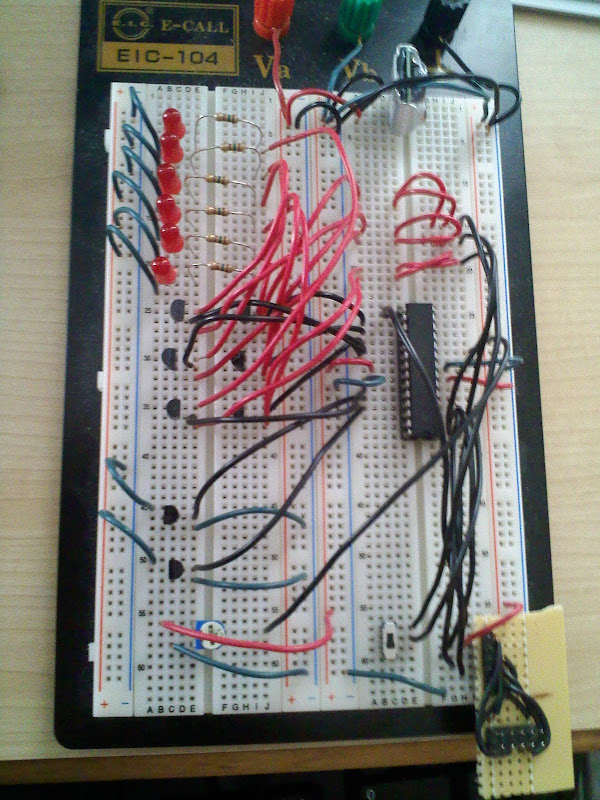
If you care for an explanation. The wires going to the bottom right are the programming wires (RESET, VCC, GND, MISO, MOSI, SCK). The black wires from the MCU to the topish right are the 3 PWM. They each get split to two. Then they go to the PNP transistors. Also, every black wire coming from the left side of the MCU is going to the transistors. From the transistors, the wires then to go the resistors (top left), then to the LEDs. From the LEDs, the green wires go the complete left side of the board. From there, then go to a place where two NPN transistors are. These transistors control what wires are connected to ground, they aren't needed yet, so they are always ON. The black wires from the NPN transistors on the bottom left go to the MCU. The potentiometer on the bottom left hasn't been implemented yet. I have it wired correctly, the red wire is from +5V, the green wire goes to GND, and the black wire is connected to ADC1 on the MCU.

