Recent Posts

Pages: 1 2 3 ... 10
1


Above are double stacked pulleys front and side views. One disc on either outside part and one disc in the center that splits the two bearings up. I have to add a black string across the bottom to prevent the yellow rope from skipping over the center pulley disc and hopping into the bearing next to it so that both ropes are sharing the same bearing and rubbing on eachother. That's bad. So a black string running across the bottom will make that jump impossible. So still have to add that. But overall, as long as tension is kept on this setup, it works well. I've tested it and it is working nice and smoothly. Still needs more testing but so far so good. You can see that all my knots and strings are coated in super glue. This is to prevent the knots from untying and just solidify everything more. The clear plastic discs are made from plastic cut out by hand from blueberry, strawberry, and sushi containers from the produce section of the local grocery store. Cakes also have this kind of plastic. It is firm but flexible with great memory to bounce back to prior shape if it is bent temporarily out of alignment. Pretty decent and nice and thin. I like it for this. I think it's less likely to break than a 3d printed disc. I cut it into these tiny discs just by eye with 4" straight titanium embroidery scissors.
2
Here are some prototype pulleys in progress of being made. I have 7 of 9 pulleys done so far for my prototype Archimedes compact pulley system design 64:1 down-gearing system. The total size of the 64:1 down-gearing system is 11cm x 6mm x 1cm. This is a very convenient form factor for placing lots of these in the elongated spaces of a humanoid robot where muscles would normally be located.


Above is a couple angles of a double pulley stacked vertically instead of side by side. Have not tested it yet but I think it should work. In this design, we have a smaller pulley attached to a larger one. The smaller one is based on a 1x3x1mm ball bearing and the larger one is based on a 2x5x2.5mm ball bearing. The smaller pulley can handle up to 3lb and the larger one can handle up to 22lb (estimated based on what I could find out but I'm not 100% sure on these, they are ball park). Each time we add a pulley we increase the torque by 2x so eventually we move from smaller to more robust, larger pulleys as we go on with the Archimedes down-gearing pulley system.
3
Attached is a good reference image set to study on a pulley block from a youtube video called "Why Snatch Blocks are Awesome" - By SmarterEveryDay.  It is a good example of a complex pulley block system worth studying imo.


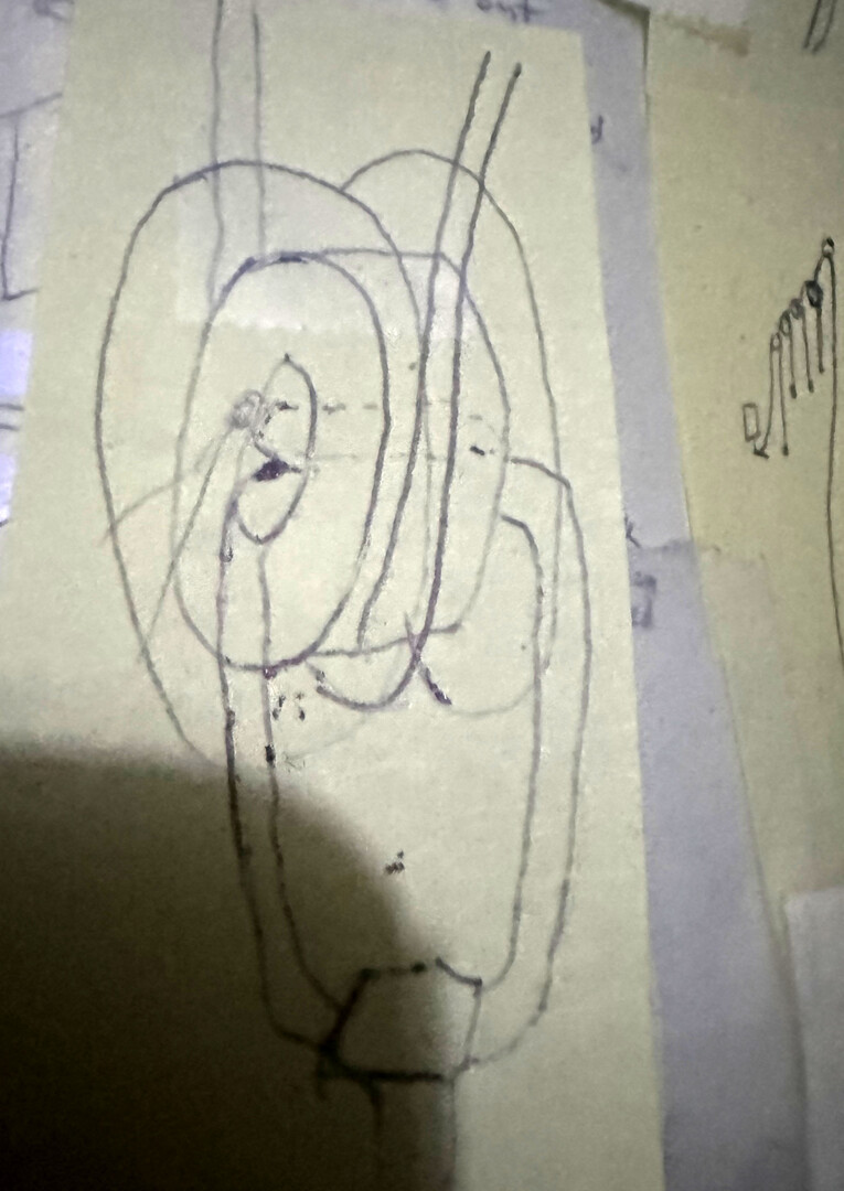
Above is my design drawing of a bearing based pulley. The bearing is in the middle and a plastic disc is on both sides sandwiching in the bearing. These discs prevent the string from coming off the outer race of the bearing. The top rope comes down, wraps around the outer race of the bearing, then goes back up. The bottom rope goes through the center of the bearing and then ties off on the bottom. This handoff between the forces of the top rope and bottom rope is where the magic happens of the mechanical advantage doubling. Trading speed for torque. The plastic discs on either side of the bearing I am able to tie snug to the bearing by threading a string through the center of both discs and the bearing and then wrapping that around the top half of the whole pulley and tying it off. I do this with another wrap going around the bottom half too. These don't interfere with rope travel and hold everything together solidly.

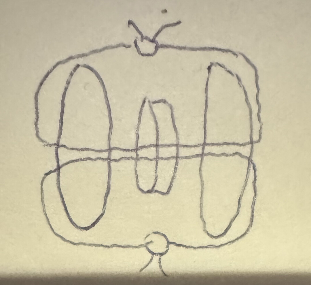
Below is a diagram where you can see the two ties I'm talking about from a side view with the two discs and the bearing spread apart so you can see everything better - this is called an "exploded view" where the parts are spread out for easier visibility.

Note: the ties that hold it together are nylon upholstery thread. The glue I'm using is 401 glue generic stuff off ebay. The plastic discs are clear plastic I salvaged from blueberry, strawberry, and sushi produce containers. That type of plastic is perfect for this. The same plastic is also found in coffee cake, other cakes, etc. It's like plastic "display" plastic that is very clear and fairly firm but very flexible. It seems ideal for pulley making. These can be cut to size with little 4" titanium straight embroidery scissors. Wearing a magnification visor for accuracy is recommended for this.

Note: I have to make custom pulleys because there are none commercially available at these tiny sizes from the shopping attempts I did (if I'm wrong on this, let me know)


I put a little super glue onto these strings pictured above to stiffen them and prevent their knot from untying and solidify everything more generally. But you should apply the glue by dipping the tip of a sewing needle into the glue so you just apply a tiny amount at a time so none gets into the bearing or any other unwanted area.

Now I am working on the actuation of a index finger first as actuating the hands is a hard challenge in robotics and has never been done with human level strength, accuracy, speed, and range of motion while simultaneously keeping all actuators within the confine constraints of a human arm between the bones and skin where muscle would be. At best, we've seen people greatly increase the size of the forearm to be the size of a thigh in order to cram in enough motors and electronics to pull this off. So they "cheated" in some sense by just upping the size rather than solving the miniaturization challenges required to fit this all inside a human form factor. So I might be the first to downsize to fit the human form factor. Anyways, that all said, the pulleys must then be very small for the fingers to pull this off as we'll need to fit a ton of pulleys into the forearms. So for this, I went with 1x3x1mm ball bearings I bought on aliexpress. They're only like $25 for 200 of them so very cheap. I will bump up to larger bearings once the torque conversion demands it. These tiny bearings can only handle I think like 3lb of force on them. So once the forces multiply in the down-gearing system enough, I will switch to bigger pulleys as needed. The next size bearings I'm using are 2x5x2.5mm bearings. These can handle around 22lb placed onto them. I'll finally switch to custom made plain bearings once I exceed 22lb of force for the last couple pulleys of the 64:1 down-gearing Archimedes compact pulley system. Each bearing in the down-gearing process has twice the forces placed onto it than the previous bearing upstream of it. So the motor is like .42lb of force coming off its shaft at 0.25cm away from its central axis point which is about where our string wrap will average, so the first bearing ups that to .84lb of force so a 1x3x1mm bearing can handle that. Next doubling is 1.68lb of force. Again, 1x3x1mm bearing can handle that. Next doubling puts us at 3.36lb force. again a 1x3x1mm bearing can handle that (although it's pushing it - we'll see in testing...). Next doubling is 6.72lb force. 1x3x1mm bearing cannot handle that much so we switch to 2x5x2.5mm bearing for that pulley. And on it goes till we hit the last couple bearings which exceed the force even the 2x5x2.5mm ball bearings can handle. For those two bearings we are going to make custom stainless steel plain bearings using stainless steel tubing I bought that just has to be cut to the length we want with a dremel to make a simple plain bearing that has no balls in it. This type of bearing can handle much higher forces because it doesn't have little balls that can be crushed. It will have more friction internally though but that's the tradeoff we have to make to keep the sizes tiny as possible. The final force the pulley system outputs is around 27lb. So 27lb of force will bend the two most distal joints of the index finger. Due to the mechanical advantage loss that happens at the joint itself, I estimate around 5.4lb of force will be all the finger joint can finally lift. So if the robot were to put its hand palm up and pull its index finger back and forth signalling a person to come over here - that movement - for that movement it should be able to pull a 5.4lb weight. That is about the same amount of weight I think my index finger could lift and with great difficulty. So it will be as strong or stronger than me on this joint pair. I say joint pair because the index finger distal two joints share the same muscle for their actuation. They move together at the same time and so just need the one motor.
4
For Sale / Re: Tracked lawn mower robot with engine and 12v 250w track motors
« Last post by gladhyundai on April 25, 2024, 07:30:15 PM »
Are you currently sold? And if I buy it, will I get a good price warranty?
5
Misc / Survey about Exoskeletons
« Last post by NRicola on April 18, 2024, 05:18:54 AM »
Hi everyone,

I would like to become more active in the field of exoskeletons - probably building an exoskeleton.
The questions are somehow always the same with every such project: Why? How come? What for? Pourquoi?

You could help me, focusing on "the right" exoskeleton. I just would like to find out, what makes sense most.
At least I would like to avoid, just building an exoskeleton only for myself. Probably it could be useful for some other people as well.

That's why I've created a short survey (<7min) to shed some light on it.
I would be very happy if you could take part in it and give me feedback:
https://yujp90be53w.typeform.com/to/mOvytIhT

I am very grateful for your feedback!
Of course, if you are interested, I could present the results here.

Best regards
Enrico  :)

6
Mechanics and Construction / Re: My Advanced Realistic Humanoid Robot Project
« Last post by artbyrobot1 on April 18, 2024, 12:12:34 AM »
here's my archimedes pulley downgear system CAD for my 2430 bldc motor for finger actuation.  This will give 64:1 downgearing.  Compare this to 180:1 standard downgear ratio in a hobby mg996r servo motor for example.  Will be a bit faster than that then but still plenty of torque with this beefy bldc motor (200w motor).  I prefer pulleys over gears since they will operate mostly silently whereas gears are noisy.  I think this pulley system is the secret sauce of my plans that I am not aware anybody has done yet.  It could be the standard for humanoids one day maybe if it is as good as I think it will be.  Still experimental but I'm going to be prototyping this soon.  I will be making my own bearings for these pulleys so the whole pulley is custom made.  Well some pulleys I'll be using purchased mini ball bearings and some pulleys I'll be making the bearings as plain bearings using stainless steel tubing which I can cut to size with my dremel to make the plain bearing.  Another HUGE benefit of pulleys over gears is gears generally are mounted to top of motor which really makes a large volumetric area taken up by the motor and downgearing which creates space concerns for fitment inside tight spaces in humanoid form factor (particularly when you use a human bone structure instead of a hollow 3d printed arm with no bones which some have done to accomodate geared servos inside the hollowed arm space).  So by translating the motor's turning by way of braided PE fishing line to a pulley system like this, you can decouple the motor from the downgearing in your CAD design, placing the downgearing in a convenient place separate from the placement of the motor which allows for creative rearranging possiblities that enable you to cram way more motors and downgearing into the very limited spaces in the robot.  The motors and downgearing is fitting where muscles would normally be in a human body so you want elongated narrow fitment options and this way of downgearing lends to that shape requirement well.  Also it is nice not to have to worry about making or buying gears which can add cost and complexity and weight and a lot of volume concerns.  The noise elimination will be huge.

I'm planning to use .2mm 20lb test braided pe fishing line on the finger motors that will run to the pulley system and then swap to 70lb test line for some of the lower pulleys where the downgearing has beefed up the torque quite a bit and the tension will be higher there so going thicker line then.  70lb test will go to fingers from the final pulley of the archimedes pulley downgearing system. 

The 70lb test PE braided fishing line (hercules brand off Amazon) is .44 mm OD and pairs well with .56mm id ptfe teflon tube I can buy on ebay.  The 20lb test PE braided fishing line (hercules brand off Amazon) pairs well with 0.3mm id ptfe teflon tube.  The tube acts just like bike brakes line guidance hose to guide the string to its desired location.  Teflon is naturally very low friction.  I may also lube the string so the friction is even lower inside the tubing.  I'd use teflon lubricant for the lube.

I will be actively CAMPAIGNING AGAINST use of gears in robots because I think they are too loud and obnoxious.  BLDC motors are quiet and pulleys should be quiet too.  Having powerful, fast, and very quiet robots is ideal for home users who don't want a super loud power drill sound coming off their home robot.  I believe this downgearing by pulleys solves all of this and aught to be the way downgearing is done for humanoid robots as the standard approach going forward. - but of course someone has to be first to do it to prove it and show a way to approach this method and I seem to be the one for this task.  Note I can't recall but maybe there was one asian robotics team that used pulleys not sure.  I decided on pulleys before I came across that team but I'm fuzzy on that team's design now.  In any case, nobody to my knowledge has fully downgeared to 32:1 or 64:1 type ratios by way of pulleys before now so I'm definitely innovating that imo.

Note on low update frequency:  I work on the robot in spurts for like 3-4 weeks then go on to other projects for months at a time before coming back to the robot.  Lately I've been thinking I should do at least one tiny thing for the robot per day as a minimum to keep it in mind and keep progress less in spurts and more steady going.  This has been working well the past few months.  I'm making much more consistent progress and also life is getting more manageable with my babies now growing up into toddlers and lots of other competing projects getting sorted out and settled more and some done.  Can't wait till I can double or triple my time commitment to the robot.  It's hard to have the progress be so slow for me.  Especially since it's such a massive undertaking that the long breaks make getting started up again intimidating especially when you forget a lot of details of where you left off.

Note also that I did work a ton on the AI for the robot and have a lot of new videos on that stuff on my youtube channel going up lately.  That has been very fun and satisfying but I've only scratched the tip of the iceberg with that.  Maybe put in 80 hours of the required 10k+ hours to really get big results LOL. 

Note: I also have decided to make my own motor controllers from scratch to cut costs and have more control and less relying on a black box situation going on.  I want my microcontrollers to directly control and monitor ever detail of the rotation of the motors and report back to my main brains PC the status of things.  I designed the electronics for this with the help of electronoobs on youtube who did a series of videos on BLDC motor controllers of various types.  He helped me understand it alot and chatgpt answered tons of my questions and helped alot too.  I have 2 blueprints for my designs for these motor controllers which are done and also did 3d blueprints for them in CAD.  I also did a prototype which I still need to finish and test.  I also made a gerber file with intentions to have JLBPCB make some flexible small motor controller pcb parts for me but they were a total ripoff on price due to the complexity of my board and their pricing structure frowning on that.  So I'll be making my own circuitboards using diy methods instead going forward.  One more reason I decided to roll my own motor controller circuitboards is the huge space constraints I'm dealing with kind of forcing my hand to make my own circuits since commercial ones are not optimized for size enough to fit in the very tight constrained volumetric areas I have to work with.  So it was basically not even optional in my case.

Ideally if my designs work out, the motor controllers I make which will be super small and flexible on flat flex boards will become commercialized products one day and so will the archimedes pulley designs or at least mini pulleys themselves be able to be bought.  But since none of this stuff exists commercially I have to make it.  The price you pay to be a frontiersman and trend setter at the forefront of new technological areas of development.  All of these factors slow me down.

On a positive note I did find a time saver/shortcut.  I bought a lifesize humanoid doll that is fairly realistic looking to use as a outer shell for the robot.  It is a TPE doll.  I have to modify it to fit my PVC medical skeleton frame significantly so.  But it is easier than starting from scratch or 3d printing everything and making molds and casts and whatnot.  I plan to cut off its skin to make a sort of skin suit for the robot and also make my exoskeleton wireframe mesh that supports the skin using the modfied, skinned doll as a guide.
7
Electronics / Use closed loop stepper motors instead of open loop stepper motors
« Last post by ben25 on April 07, 2024, 02:17:07 AM »
Hello everyone,
My 3D printer has a slow printing speed. Once the speed is increased, the motor will easily lose synchronization, and the accuracy and success rate will drop significantly. If I want to solve these problems, can I use a closed loop stepper motor instead of an open loop stepper motor? A motor similar to this: https://www.oyostepper.de/goods-533-Nema-17-Closed-Loop-Schrittmotor-09-Grad-44-Ncm-mit-Encoder-1000CPR-Schrittmotoren-mit-Geschlossenem-Regelkreis.html
8
Misc / Re: Articulated Robot Question
« Last post by grindiffer on March 06, 2024, 08:15:11 PM »
Does a cylindrical robot with 2 vertical rotary joints (one on base, one on arm) make it articulated?
If so, when I remove one rotary joint (base or arm), does that make it non articulated?
Thanks
At the present time, this is completely possible. I believe that in the future robots will become even more flexible.
9
Mechanics and Construction / Re: Trumpet Playing Robot... how does it work?
« Last post by piesobese on February 11, 2024, 03:15:47 AM »
All they have to do is vibrate the air entering the trumpet at the frequency they want to influence the pitch.  Lips do this for humans, but my guess is that they used some sort of flapper inside the mouth of the robot.

Here is a better view of a couple Aerophone playing robots.  Toyota's Robot Quartet Band.  You can see there is nothing protruding from the mouth, and the orifice is smooth.
I was truly enlightened with this new perspective.
10
Misc / American Robots 1978 robot build plans $200 reward
« Last post by crmfghtr on January 30, 2024, 10:57:24 AM »
I had these plans from American Robots in 1979 that would still hold up today!  I lost them.  They were for a 5 foot robot that resembled Robby The Robot, with working claws motors etc.  I lost them when I moved once and have been hunting for them ever since.  Going to be hard to recover something that old but here is hoping!
Pages: 1 2 3 ... 10

data_list