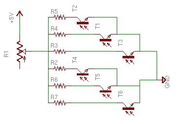
i have 6 phototransistors with a resistor network to act as the divider, the output is between the phototransistor and the resistor
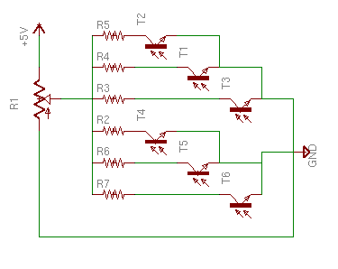
but, if i wanted to lower all the output voltages, should i use diagram 1 or 2?
1 uses a variable resistor to add to the resistance to all of the other resistors, but i'm not sure because one change in one sensor might affect another sensor's output.
2 uses a potentiometer to adjust the upper limit but i'm not sure if it works.
1:
2:
this is for my new mini sumo bot, i need to be able to adjust the overall readings so it works in a high light enviroment, if the adc result is under 30 it goes into passive tracking mode and i don't want that to happen if it sees some spotlight or something.

