Author Topic: PCB layout  (Read 2302 times)

0 Members and 1 Guest are viewing this topic.

Offline DoktorTopic starter

  • Beginner
  • *
  • Posts: 1
  • Helpful? 0
PCB layout
« on: April 04, 2010, 03:40:24 AM »
Hello everyone!
I'm new to robots, and to the forum, too.  ;D
I'm working on a project that quite similar to the 50$ bot, but not exactly the same. I'm using DC motors with a motor driver circuit. I'm building that schematic: http://www.hobbielektronika.hu/kapcsolasok/files/354/kapcsrajz.jpg.
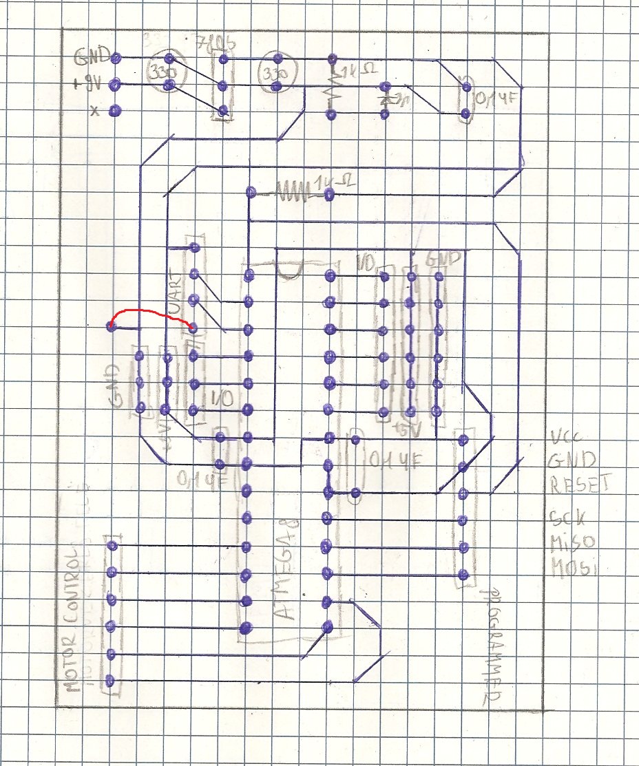
I've designed a PCB layoutfor it, but because this is my first robot and first PCB desing, i'm not sure if it's correct.
I'd like someone to check it according to the schematic.

Here's the PCB layout (i can't even use EAGLE, so i used paper and pencil :D ):


Bye and thanks for all the replies.

EDIT: the red line is a piece of wire, i can't made it without a crosswire.
« Last Edit: April 04, 2010, 04:01:09 AM by Doktor »

Offline Soeren

  • Supreme Robot
  • *****
  • Posts: 4,672
  • Helpful? 227
  • Mind Reading: 0.0
Re: PCB layout
« Reply #1 on: April 04, 2010, 01:58:11 PM »
Hi,

Perhaps you can use this.
Regards,
Søren

A rather fast and fairly heavy robot with quite large wheels needs what? A lot of power?
Please remember...
Engineering is based on numbers - not adjectives


SMF spam blocked by CleanTalk