
 Search Here
MISC
Parts List
Robot Forum
Chat
Member Pages
Axon MCU
Robot Books
Shop
Contact
SKILLS
How To Build
A Robot
Tutorial
Calculators
Mechanics
Programming
Miscellaneous
Robots
Space
HARDWARE
Actuators
Batteries
Electronics
Materials
Microcontrollers
Sensors
SCIENCE
Robot Journals
Robot Theory
Conferences

Technical details for those technically inclined.
 |
Axon Datasheets App for Android Offline version of Axon series datasheets - for those emergency situations when you don't have internet access. |
FREE
(download at Android Market) |
DIMENSIONS
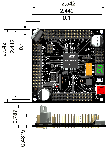
Total weight is 34 grams.
Four 4-40 screw holes make mounting onto your robot easy.
DOCUMENTS
-
Axon II schematic
ATmega640 Datasheet
USB to UART Bridge Datasheet and App notes
Axon II printout (a 1:1 ratio printout of the Axon)
 ATmega640 pinout quick reference
VOLTAGE TOLERANCES
-
Unlike the original Axon, the Axon II has two different power configurations.
The default battery configuration requires just one battery to operate the Axon II - just like the original Axon. All Axon IIs are manufactured and shipped in this default configuration. You can also attach additional batteries in parallel on the unregulated battery bus (all batteries must be the same voltage, battery type, and charge level) as needed.
The dual battery configuration allows you to use a small stable battery for powering sensors and the ATmega640, while a much larger less stable power supply can be used for motors and/or servos. In this configuration, the battery meant to be regulated goes on the BAT header, while the other battery goes anywhere on the unregulated battery bus. To enable this configuration, flip over your Axon II and remove the small solder trace between BAT and G5. This trace acts as a high-current jumper.
For an example on how to change the battery configuration, please see this video:
Absolute minimum required voltage is 5.35V. If at any time the voltage drops below this amount, even for a milli-second, the Axon II will reset. The recommended battery voltage is 6V to 7.2V (a 6V 1000mAh+ NiMH battery works great). Maximum voltage at 16V, however most servos will have reduced lifetimes at voltages above ~6V and can quickly fail at voltages ~7.2V+.
There are three power buses. ADC pins 0 to 15 are regulated at 5V, while all other pins are directly connected to your battery. There is also two 3.3V output pins (see current tolerances).
The Axon II has polarity protection features, meaning that it is designed to protect itself if you accidentally plug your battery in reverse. However, it will NOT protect any external component(s) connected to the unregulated battery bus.
The 3.3V power bus is NOT protected against polarity or power surges, so be careful or you'll fry your USB.
This is how the pins are set up in terms of power.
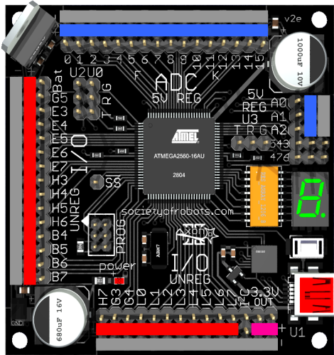
Pins	Voltage
Bat	battery (input)
G5-B7	battery
H7-L7	battery
A0-A2	5V regulated
0-15	5V regulated
3.3V	3.3V (output)
G	ground
-	ground
SPECIAL PINS
-
In addition to normal digital I/O functionality, some pins come with additional special features.
Hardware PWM
Hardware PWM is perfect for creating a perfect high frequency squarewave without
any cost to the processor. Servos using hardware PWM can only be used on 16 bit pins, while regular DC motors can be used on any PWM pin.
8-bit timer pins: G5 (T0), H6/B4 (T2)
16-bit timer pins: B5/B6/B7 (T1), E3/E4/E5 (T3), H3/H4/H5 (T4), L3/L4/L5 (T5)
UART
The UART is great for sending and receiving serial data, such as from a GPS, a camera,
external memory, other microcontrollers, etc.
pins: U0, U2, U3, U1 is connected to USB
ADC
The ADC, or analog to digital converter, is great for reading in analog sensor data
(Sharp IR, photoresistor, accelerometers, gyros, etc).
pins: 0-15 (F0-F7, K0-K7)
External Interrupts
External interrupts are useful for triggering interrupt code when important external events occur.
Use these for encoders, sonar, and other time important sensors.
pins: E4-E7 and D0-D3 (I2C, UART 1 pins)
CURRENT TOLERANCES
-
All ADC power bus pins get power from the 5V LDO voltage regulator with maximum allowable current of 1.5A.
If the regulator overheats, such as from overuse or shorting, it will protect your Axon by triggering a
temporary thermal shutdown. Adding a heat sink to the regulator will allow for higher power consumption.
See the FAQ for more on heat sinks.
The Axon II has been tested to handle at least 6A on each power bus, but can in theory safely handle up to ~13A. Placing your high current draw components near the battery can up this number. This limitation is entirely based on power bus tracing thickness, meaning that if you require higher currents you must make your own separate power bus. Using multiple batteries distributed along the power bus can reduce current across individual traces.
Individual I/O pins can supply about ~20mA power, each. Exceeding this number could damage/fry the I/O pin.
The Axon II also has a special regulated 3.3V output bus, great for components or sensors that require this low voltage. This pin cannot supply more than about 73mA, or 90mA if you aren't using USB. If you find that USB becomes unstable or fails to work when using this output, make sure you aren't overdrawing current and place a 4.7mF tantalum capacitor (polarized) between 3.3V and ground. Don't use any device with 3.3V that is likely to transmit a power surge during use.
If you exceed the specs of the 3.3V output, you can permanently damage the USB. Do not just plug anything into it without first verifying the current draw is ok and that no voltage transients will occur.
You must also keep in mind the current tolerances of the included Hitec 572125S on/off switch.
Quoting Hitec:
"A conservative estimate would be in the 10 amp range for the 572125S and 16
amp range for the 54407S. But again these are just estimates."
- Hitec Sales Manager
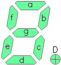
LED DISPLAY
-
The Axon II has an in-built LED display. It can display any number you want,
and the small dot works as a status LED. If you want to just activate a particular
LED on the display, use this as a guide.
NOISE SUPPRESSION
-
All electronics creates electronic noise and sudden voltage spikes/drops that
can potentially cause problems.
The Axon II has been intentionally designed to minimize this noise, and in fact during
extensive tests I found no detectable (non-negligible) noise for robotics purposes.
However, your needs may be different. If you find
you are using highly sensitive sensors, I recommended attaching additional noise
suppression ceramic capacitors in parallel with the regulated power bus.
CAD FILES
-
Feel free to contact me if you would like
to share your CAD files for the Axon.
Axon II: AutoDesk Inventor CAD Files (1.7mb)
This includes a .stl file.
No Sketchup CAD files are currently available. Let me know if you made one!
If you'd like to create your own CAD, feel free to download the Axon II texture image.
If you have a SolidWorks design of the Axon II, let me know!
Society of Robots copyright 2005-2014