
 Search Here
MISC
Parts List
Robot Forum
Chat
Member Pages
Axon MCU
Robot Books
Shop
Contact
SKILLS
How To Build
A Robot
Tutorial
Calculators
Mechanics
Programming
Miscellaneous
Robots
Space
HARDWARE
Actuators
Batteries
Electronics
Materials
Microcontrollers
Sensors
SCIENCE
Robot Journals
Robot Theory
Conferences
Finite Element Analysis
Introduction to FEA
Finite Element Analysis is a method to computationally model reality in a mathematical
form to better understand a highly complex problem.
What does 'finite element' mean? Well, in the real world, everything that occurs results from the interaction between atoms (and sub-particles of those atoms). Billions and billions and billions of them. If we were to simulate the world in a computer, we would have to simulate this interaction based on the simple laws of physics. However, no computer can process the near infinite number of atoms in objects, so instead we model 'finite' groups of them.
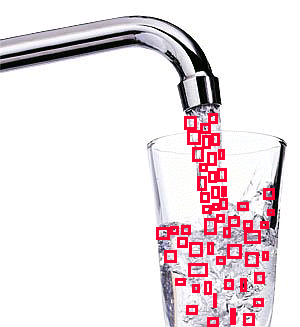
For example, we might model a gallon of water by dividing it up into 1000 parts and measuring the interaction of these linked parts. If you divide into too few parts, your simulation will be too inaccurate. If you divide into too many, your computer will sit there for years calculating the result!
Here is an example of flowing water being divided up into finite parts:

Equations of equilibrium, in conjunction with applicable physical considerations such as compatibility and constitutive relations, are applied to each element, and a system of simultaneous equations is constructed.
Why use FEA?
Simulation in general is always a good idea, as it lets you test designs and ideas
without spending money or effort actually building anything. And in some cases, an
experiment would be impossible or too expensive to carry out
(satellite launching, aircraft aerodynamics, etc) so a simulation would be the next best thing.
By using simulation, you can find fault points within your designs, simulate ideas as you think of them, and even quantitize and optimize them. I personally even use simulation to verify my theories - if the theoretical simulation matches what actually happens, then my theory is proven!
Sometimes you can hand calculate certain designs. But sometimes a design can be too complex, making FEA great for non-symmetric problems with ultra-complicated geometries.
Warning Against FEA
Before you get the idea of 'hey this is really neat, creates pretty pictures, and can tell
me lots of useful information', most problems can be solved using elementary equations on paper/pencil.
You simply do not need to invest all this time to solve such problems in simulation.
More importantly, 'garbage in means garbage out.' If you don't understand the problem,
you will end up setting up the problem incorrectly, and the result will
be incorrect. If you didn't understand what was happening, how would you know if you
simulated it correctly? You must understand exactly what is going on to know what is and isn't garbage.
What does this mean? Pick up some introduction material! Don't expect to do advanced computational fluid simulations without knowing what a boundary layer or a Reynolds number is! Want to do a bending beam analysis? You need to know things such as what the modulus of elasticity is!
Preprocessor (Setting up the Problem)
The preprocessor is what you use to set up the problem - defining material properties and boundary conditions
and such. For example, if you were doing CFD, you'd want to define the fluid density (air, water, oil, etc),
viscosity, slip or no slip conditions, etc. If you haven't already started reading up on the basics, the preprocessor
will be quite difficult if not impossible to understand. Wikipedia is your friend!
Meshing (Defining Elements)
After you design your part in a CAD program, you'd want to mesh it.
Meshing is where you define a finite number of elements to represent the geometric structure.
There are a few basic things you must know about meshing. First is the number of elements. More elements
means higher accuracy. More elements also mean more computational time is required to find a solution.
There will always be a balance between time to solve the problem, and the level of error you consider
acceptable (5% error? 1%? .001%?). Perhaps you are thinking that smaller error is worth the wait. Well a basic
CFD simulation can take ~2 hours. And that's only if you did it right the first time . . . I've run
some simulations that take nearly 2 days on fairly expensive computers!
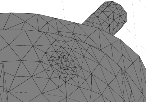
This following example is a very rough meshing of my robot fish that I used for a CFD (computational fluid dynamics) analysis. I created a special simplified CAD of my robot fish, removing sharp corners, internal features, unnecessary edges, etc. to greatly speed up CFD analysis.
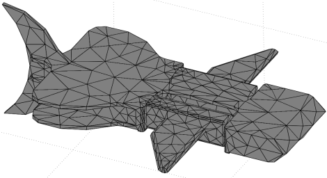
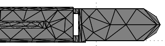
Looking closely at the above image, you can see that there is a jagged rough triangular edge on the front of the robot. However in my design I called for a smooth rounded front edge! The reason? Insufficient meshing. Increasing the mesh density, I now get this:

This meshing turned out to be appropriate enough for the solution accuracy that I required. Below is what the rounded front now looks like. Not perfectly round, but it will do. There are many other tricks/methods you can employ but too detailed to go into for this tutorial.
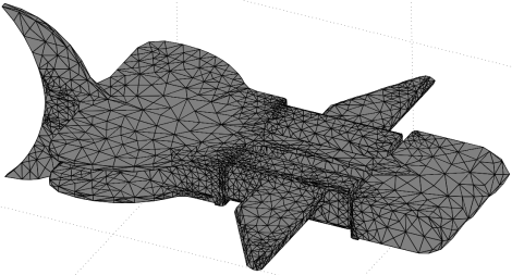
However, what if I wanted something more accurate? Below is an even higher density mesh. But remember, denser the mesh, greater the computational time/memory required.
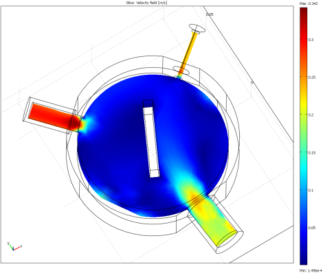
More examples . . . For fun I modeled this stirring chamber shown below. It has an internal chamber with three pipes of different diameters. A fluid enters in one pipe, then gets mixed by turbulence and finally exits the other two pipes.
Now if I were to optimize this stirring chamber, how would I know how well it mixes without building it? CFD!
First, I meshed the chamber and then I ran a quickie simulation to verify I set everything up properly. Looking around a bit, I noticed a mistake . . . One of the outlet pipes was so poorly meshed it wasn't even round!!! Notice the square opening below:
The rest of the simulation was fine, so what I did was improve the mesh just around the pipe inlet only. Why just the pipe? Increasing the mesh of the entire device would have led to wasted computational time! Basically, you want finer meshes around sharp curve areas and rougher meshes around areas that have few features and small gradients. This is the improved mesh:
Rerunning the simulation with the locally improved mesh, I get this much more accurate result:
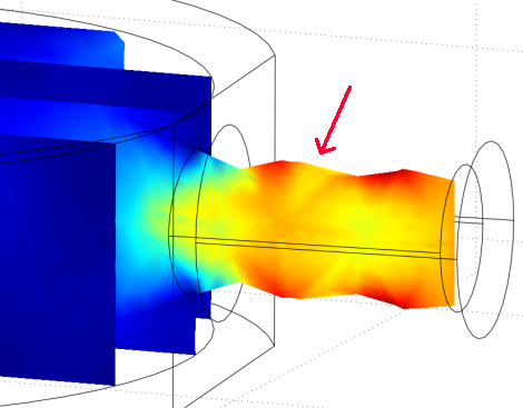
Looking at my solution (plotted as velocity field slices) I found several more obvious errors, each resulting from an improper meshing. Looking at the inlet pipe, you can see a saw-tooth like shape (see red arrow), and a corresponding high pressure buildup at each 'tooth'. This pipe must be smooth!
So I increased the mesh density some for just that pipe to remove the problem and got this different and more accurate result:
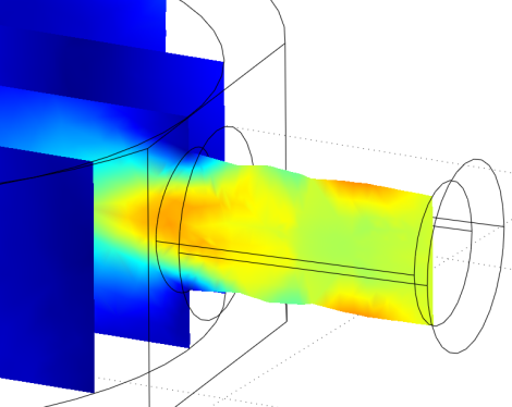
However there are still jagged edges in the above image. Since it wasn't acceptable, and I didn't mind the significantly higher computational time required for yet a 3rd CFD run, I then got this near perfect input pipe:
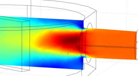
This is what the velocity field (red for fast and blue for slow) looked when finished:
CFD - Computational Fluid Dynamics
Now you have probably been wondering what exactly is CFD? There are various methods
to do this, but basically imagine a computer keeping track of units of water molecules
and applying the basic laws of physics on them. The computer then calculates the interaction
between millions/billions of these units, recording resultant motions and forces.
For example, going back to my stirring part, I wanted to measure the stir. To do this, I need a particle tracing - called so because a line is drawn of the path the particle takes. I also have the velocity recorded while the particle traces that path, resulting in the different colors.
This is the result:
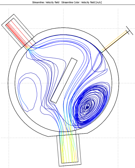
Notice the swirl at the bottom right of the above image. This means its mixing really well. Success? Nope - you will also notice that most of the fluid that enters the swirl never exits, meanings its trapped stagnant water! To correct for it, I'd have to reposition the angled plate in the center of the chamber and redo the 2 hour simulation.
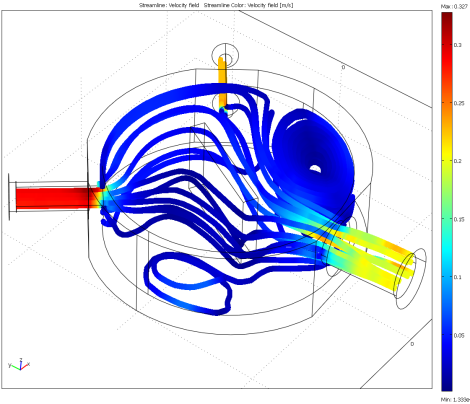
Here is a view of it in 3D, using ribbon cable tracing:
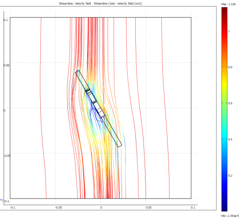
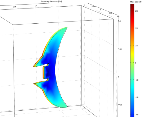
I also did a particle tracing about my robot fish tail fin to see how it interacted with water flowing at an angle. I wanted to test the effectiveness of the tail as a rudder:
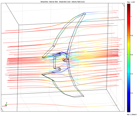
A top view of the robot fish tail:
But I can do so much more! Each element of fluid applies a force against objects - remember that the program determines interactions using physics equations. I can not only determine this force, but also pressure distribution. Now I can determine what could be changed to optimize that pressure distribution and minimize material cost simultaneously.
Here is an example of a pressure distribution on my robot fin. Calculating the total force, I can easily determine how effective of a straightening rudder this tail fin can be.
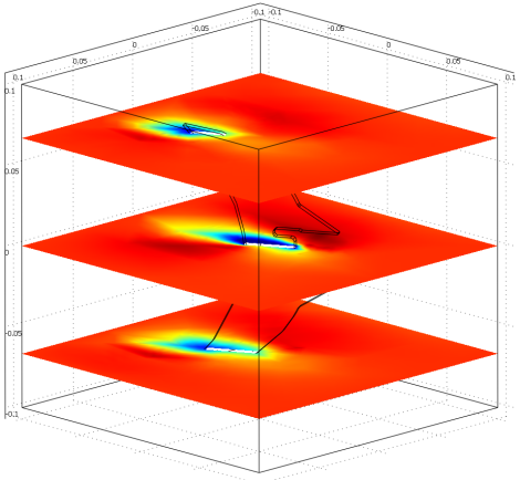
And a plot of the fluidic velocity at several cross-sectional layers across the fish tail fin. Red is fast and blue is slow:
Stress Analysis
All objects bend, compress, and otherwise change shape as forces are applied to them. What an engineer
wants to know is does this shape change detrimentally affect the reliability/functionality of a design?
For example, you are designing some complex shaped bridge, and want to make sure the bridge does
not flex more than 1" under the weight of a large truck.
Or what if you are designing a robot arm and want to know how much it flexes if it lifts a 2 pound kitten (to throw, of course)? It is extremely important to design robot arms to be highly rigid, as the flexing greatly reduces positional accuracy.
You also want to make the arm as light as possible to save money on the actuators (heavier robot arms need stronger motors). To do this you would reduce material use as much as possible. However, reducing material also reduces rigidity. So you need to determine both how much material to remove, but also where to and where not to remove that material.
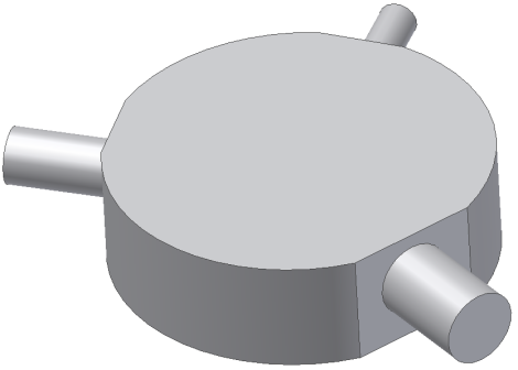
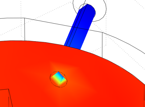
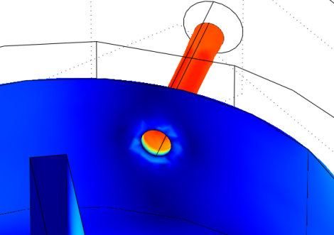
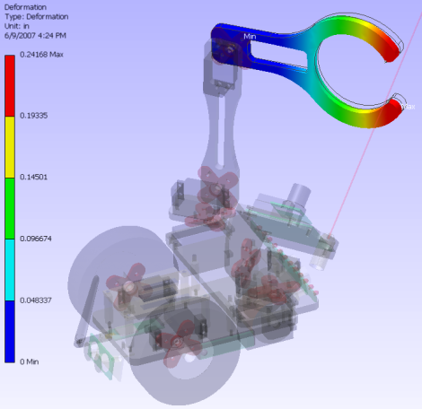
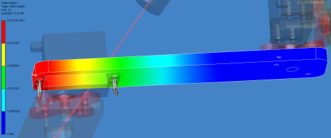
Here is an example of a stress analysis that I ran on my ERP robot arm I am currently working on. I designed the arm knowing basic principles of stress analysis, selected a material known to be rigid and entered that data into the preprocessor, and then applied forces that were expected. The output result was expected deflection measured in distance. In this below image, I applied 2 pounds in the gripper area and measured a deflection of 1 centimeter. This means that my position error will be 1 centimeter. If I were to decide this error was unacceptable, I would change the arm shape, add material etc. and rerun the FEA stress analysis.
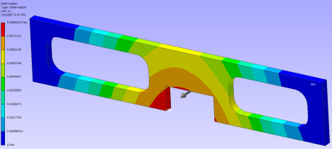
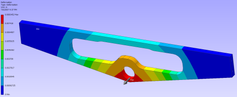
Here are a few more examples of stress analysis problems I had to solve.
This below example was my first design for part of the robot arm. I just went with a big block of material, and poked some holes into it. The logic was that these holes would significantly reduce weight (good) but only minorly affect bending deflection (deflection is bad). Turns out, after FEA analysis, that deflection was insignificant, and that I can take away much much more material.
So this is what I then designed it to look like after determining that the deflection was acceptable:
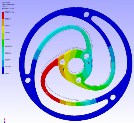
And a few more random stress analysis runs I did for other projects. The arrows show the direction of force, while the ends of each part were fixed as rigid:
One neat useful trick to use with FEA is to design a robot wheel suspension system out of a single part as shown below. To learn more, check out my Robot Suspension System Tutorial.
Heat Transfer
Yeap, you can even measure how heat passes through objects. Of course before you can do this simulation,
you must understand the basic concepts of heat transfer. Go read up!
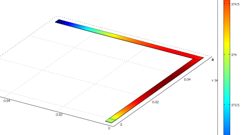
Now there are many types of heat transfer problems, but one that I was curious about is how heat is distributed in a trace in a printed circuit board when I apply excessive current. I basically wanted to get a good estimate on temperature to know how much I can heat up a wire before it causes permanent damage to the PCB and other surrounding material. Of course there are already engineering guidelines to determine this for you, but I was just curious and felt it to be a perfect first example.
To make it slightly more interesting, I am doing this to a power bus of one of my circuit designs, and I also included a 90 degree bend in it to see what happens for weird shaped tracings. It turns out that temperature distribution is pretty much uniform (varying only 2 degrees F) no matter the shape, and that these tracings get pretty darn hot with just a few amps applied!
I had to set up various boundary conditions, such as how much heat can the surrounding PCB absorb (not very much), as well as thermal transfer to the surrounding air (also not very much).
Post Processing (Results, Visualization)
Post processing is the method of converting calculated raw data to something useful - such as the pretty
pictures you see in this FEA tutorial.
Post processing is where you select which display graphs you want, but also where you determine sum force,
pressure, the angle of the force, temperature, distribution, particle tracing, etc. Understanding the fundamental basics
of a problem will definitely help you make the most of the post processor.
I want software!!!
Expensive. Expensive. Expensive.
Impressed by what I have shown you above, you have probably decided that you want to add FEA technology to
improve the designing process of your own robot. Well, let me just be straight with you - its EXPENSIVE!!!
And I don't just mean a month of salary, I mean $5k+. And that doesn't include the basic CAD software you
need to just model your part. If you have access to that type of money (I work for the US Navy), then
check out the Google ads distributed throughout this page for more information. The ads at the very
top right tend to have links to good FEA software.
My CFD and heat transfer simulations were done using COMSOL.
My stress analysis was done using ANSYS. The 2008 version of AutoDesk Inventor has ANSYS built in. Solidworks also has a stress analysis solver called COSMOS.
For links to FEA and CFD software, check out the Robot Software List.
Perhaps in a few years the price of this software will go down to that which we hobbyists can afford, but until then, keep dreaming! Its what we robot builders are best at =)
Society of Robots copyright 2005-2014