
 Search Here
MISC
Parts List
Robot Forum
Chat
Member Pages
Axon MCU
Robot Books
Shop
Contact
SKILLS
How To Build
A Robot
Tutorial
Calculators
Mechanics
Programming
Miscellaneous
Robots
Space
HARDWARE
Actuators
Batteries
Electronics
Materials
Microcontrollers
Sensors
SCIENCE
Robot Journals
Robot Theory
Conferences

Adding UART Functions to AVR and your $50 Robot
To add UART functionality to
your $50 Robot
(or any AVR based microcontroller) you need to make a few minor modifications to your code
and add a small amount of extra hardware.
Now of course I could just give you the code for you to use right away and skip this tutorial, or I can explain how and why these changes are made so you can 'catch your own fish' without me giving it to you in the future . . .
Now about the speed increase . . .
We will be using the maximum frequency that your microcontroller can handle without
adding an external crystal. How do you know what that frequency is?
From the datasheet of your ATmega8/ATmega168, we can find: "By default, the Internal RC Oscillator provides an approximate 8.0 MHz clock." Listed in the 'System Clock and Clock Options->Calibrated Internal RC Oscillator' section.
Since we do not have an external crystal, we will configure the entire system (all individual components and code) to 8MHz. If you want a different frequency, I will also show you how to change it to your frequency of choice.
Open up your makefile, and add in rprintf.c and uart.c if it isn't already there:
# List C source files here. (C dependencies are automatically generated.)
SRC = $(TARGET).c a2d.c buffer.c rprintf.c uart.c
These are AVRlib files needed to do the hard UART and printf commands for you.
If you are using the $50 Robot source code, then you already have AVRlib installed and ready to use (so don't worry about it). Otherwise, read the instructions on installing AVRlib.
Also, look for this line towards the top:
F_CPU = 3686400
and replace it with your desired frequency. In this example we will use:
F_CPU = 8000000
Open up SoR_Utils.h and add in two AVRlib files, uart.h and rprintf.h:
//AVRlib includes
#include "global.h"	// global settings
#include "buffer.h"	// buffer function library
#include "uart.h"	// uart function library
#include "rprintf.h"	// printf library
//#include "timerx8.h"	// timer library (timing, PWM, etc)
#include "a2d.h"	// A/D converter function library
Now your compiler knows to use these AVRlib files. If you aren't using SoR_Utils.h, just add these lines at the top of your code where you declare includes.
I recommend not using the timer because its default interrupt settings will cause your servos and UART to spass out . . .
Open up global.h and set the CPU to 8Mhz:
#define F_CPU 8000000 // 8MHz processor
Now power up your microcontroller and connect it to your AVR as if you were to program it:
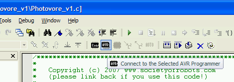
Now BE VERY CAREFUL IN THIS STEP. If you push the wrong fuse, there is a possibility you could permanently disable your microcontroller from being further programmed. BAD JU-JU!!!
Click the Fuses tab (see below image), and uncheck 'Divide clock by 8'. Having this setting checked makes your clock 8 times slower. Having a slower clock makes your microcontroller more efficient, and unless your algorithm requires a lot of math, a fast processor isn't needed. But in this case we want a fast UART speed, so we need the faster clock.
Now check the 3rd 'Int. RC Osc. 8Mhz'. By default this should already be checked, but I'm noting it just in case. If you were using a crystal or a different frequency, just scroll down in the Fuses tab for other options.
as shown here:

Then push Program and you should get a message that looks something like this:
Entering programming mode.. OK!
Writing fuses .. 0xF9, 0xDF, 0xE2 .. OK!
Reading fuses .. 0xF9, 0xDF, 0xE2 .. OK!

Fuse bits verification.. OK
Leaving programming mode.. OK!
Please note that the $50 Robot was designed for the lower clock speed. What this means is that all your functions that involved time will operate 8 times faster. In terms of processing this is great! But all your delay and servo commands must be multiplied by 8 for them to work again.
For example,
delay_cycles(500);
servo_left(45);
must now be
delay_cycles(4000);//500*8
servo_left(360);//45*8
Or if you are really really lazy and don't care about timing error, go into SoR_Utils.h and change this:
void delay_cycles(unsigned long int cycles)
	{
	while(cycles > 0)
		cycles--;
	}
to this:
void delay_cycles(unsigned long int cycles)
	{
	cycles=cycles*8;//makes delays take 8x longer
	while(cycles > 0)
		cycles--;
	}
Now we need to select a baud rate, meaning the speed at which data can be transferred. Typically you'd want to have a baud of around 115.2k. This is a very common speed, and is very fast for what most people need.
But can your microcontroller handle this speed? To find out, check the datasheet. For my ATmega168, I went to the 'USART0 -> Examples of Baud Rate Setting' section and found a chart that looks something like this:

I immediately found the column marked 8.0000 MHz (the internal clock of your microcontroller), which I circled in green for you. Then I went to the row marked as 115.2k, marked in blue. Now what this means is that your UART can do this baud rate, but notice that it says the error is 8.5%. This means that there is a good chance that there will be syncing problems with your microcontroller.
Error arises from the fact that Fosc is usually not a standard UART frequency, so the baud rate when you divide Fosc by some number isn't going to be a standard UART frequency.
Rather than bothering with this possible problem, I decided to go down a few rates to 57.6k (circled in red). 3.5% could still be a bit high, so if you have problems with it, go down again to 38.4k with a .2% error (mostly negligable).
So what error rate is considered optimal or best? It depends entirely on your hardware and so I don't have an answer for you. If you want to learn more, feel free to read about how asynchronous serial transmission is 'self synchronizing'.
The other option is to set the U2X register bit to 1 (default is 0), meaning the error at 115.2k is now only -3.5%. This doubles the UART speed, which can sometimes make it possible for you to achieve baud rates closer to standard values. If you take a look at the formulas for calculating baud rate from the value of the UBRR (baud rate) register, the error rates should make sense:
U2X = 0 => baud rate = Fosc / 16 / (UBRR + 1)
U2X = 1 => baud rate = Fosc / 8 / (UBRR + 1)
Be aware that even if your microcontroller UART can operate at your desired baud, the adaptors you use might not be. Check the datasheets before deciding on a baud rate!!!
It turns out my RS232 Shifter is rated for 38400 in the datasheet, so thats the baud I ended up with to do this tutorial.
Now after deciding on baud, in the file SoR_Utils.h (or in your main if you want) add the following code to your initialization (using your chosen BAUD rate):
uartInit();  // initialize UART
uartSetBaudRate(38400);// set UART baud rate
rprintfInit(uartSendByte);// initialize rprintf system
Relax, the hard part is done!
Now we need to add a line in our main() code that uses the UART.
Add this somewhere in your main() code:
//read analog to display a sensor value
rangefinder = a2dConvert8bit(5);

//output message to serial (use HyperTerminal)
rprintf("Hello, World! My Analog: %d\r\n", rangefinder);
You don't actually need to output a sensor value, but figured I'd show you how now so you can try it out on your robot sensors.
The last programming step.
yaaaaayyyy! =)
Save and then compile your code like you normally would:
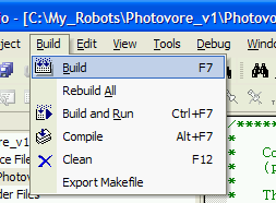
Software is done!
Now for the hardware.
I will assume you already read about adaptors for the UART and know that you have just four wires to connect to your robot:
5V
Ground
Tx
Rx
Now plug the power connections (regulated 5V and ground) into an unused header on your circuit board just like you would a sensor (the sensors use regulated 5V).
Then plug the Tx of your adaptor into the Rx header of your microcontroller, and then the Rx of your adaptor into the Tx header of your microcontroller. Don't know which pin is which? Check the datasheet for the pinout and look for RXD and TXD. Or look at the $50 Robot schematic.
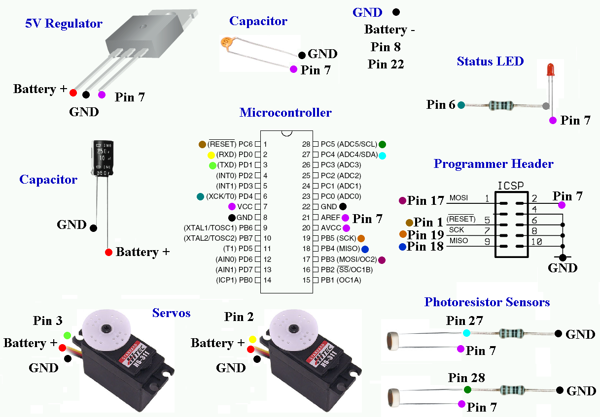
It just so happens that you probably have servos on pins 2 and 3 - oh no!
Don't worry, just move your servos onto a different pin, such as 4 (PD2), 5 (PD3), and/or 6 (PD4).
To move the servos to a different port in code, find this in SoR_Utils.h:
void servo_left(signed long int speed)
	{
	PORT_ON(PORTD, 0);
	delay_cycles(speed);
	PORT_OFF(PORTD, 0);//keep off
	}
and change '0' to the new port. If you wanted port PD2, then use '2':
PORT_ON(PORTD, 2);
delay_cycles(speed);
PORT_OFF(PORTD, 2);
Don't forget to make that change for your other servos, too.
(and of course, save and compile again)
This is what my hardware plugged in looks like (click to enlarge):

Notice how I labeled my wires and pins so I didn't get them confused (with the result of maybe frying something). I used wire connectors to connect it all. At the top right is my RS232 Shifter and at the bottom right is my RS232 to USB adaptor.
Let's do a quick test. Chances are your adaptor will have a transmit/receive LED, meaning the LED turns on when you are transmitting or receiving.
Turn on your robot and run it.
Does the LED turn on? If not, you might be doing something wrong . . .
My adaptor has two LEDs, one for each line, and so my Rx LED flashes when the robot transmits.
Now you need to set up your computer to receive the serial data and to verify that its working.
If you are using an adaptor, make sure it is also configured for the baud rate you plan to use. Typically the instructions for it should tell you how, but not always. So in this step I'll show you one method to do this.
Click:
Start->Settings->Control Panel->System
A new window will come up called 'System Properties'. Open the Hardware tab and click device manager. You should see this:
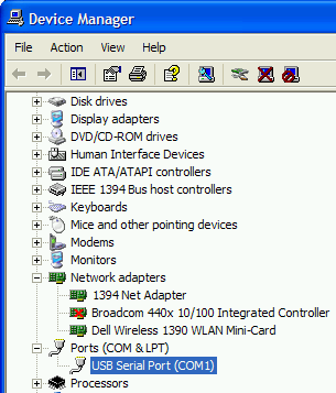
Go to Ports, select the one you are using, and right click it.
Select Properties. A new window should come up, and select the Port Settings tab:
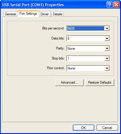
Now configure the settings as you like. I'd recommend using the settings I did, but with your desired baud rate.
This is the last step!
To view the output data, use the HyperTerminal tutorial to set it up for your desired baud rate and com port.
Make sure you close out the AVR programming window so that you can free up the com port for HyperTerminal! Two programs cannot use the same com port at the same time (a common mistake I always make).
Now if you did everything right, you should start seeing text show up in hypterminal:

If it isn't working, consider doing a loop-back test for your UART debugging needs.
You're finished! Good job!
Society of Robots copyright 2005-2014