
 Search Here
MISC
Parts List
Robot Forum
Chat
Member Pages
Axon MCU
Robot Books
Shop
Contact
SKILLS
How To Build
A Robot
Tutorial
Calculators
Mechanics
Programming
Miscellaneous
Robots
Space
HARDWARE
Actuators
Batteries
Electronics
Materials
Microcontrollers
Sensors
SCIENCE
Robot Journals
Robot Theory
Conferences
ON YOUR MICROCONTROLLER

The Microcontroller Clock
Any digital processor needs a clock. On every clock cycle your processor will do something.
Faster the clock, the more things your processor will do.
Modern microcontrollers all have built in clocks, however this tutorial will show how you can add a much faster external one to soup up your processor.
There are four types of clocks:
Silicon Oscillator
Resistor-Capacitor (RC) Oscillator
Ceramic Resonator
Crystal
I'm not going to go into details of each. The silicon oscillator is the type built in to your microcontroller - free and easy, but not very fast. The RC and ceramic oscillators have advantages that you can google up. You however want to use the crystal unless money or board space comes up at a huge premium. If you are a hobbyist, or generally don't know what you are doing, I recommend the crystal hands down.
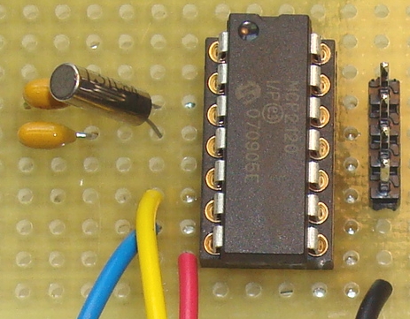
So what does a crystal look like? Well it varies a lot. For example, here its a vertical can shape. Notice the two capacitors right next to it:
And here on the Axon its a SMD rectangular shaped chip, with two caps also next to it:
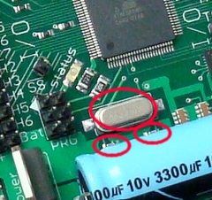
Bear in mind that a crystal can look like any other chip, too. But most often you'll see it right next to a microcontroller with two capacitors next to it.
I'll now go into how you can add a crystal to your microcontroller.
Selecting UART Speed
If you plan to use UART for say USB or TTL data transfer, you need to decide on
the operating frequency you wish to use now. The reason for this is different crystal frequencies
are optimal for different baud rates (9600bps, 115.2kbps, etc).
Now open up that ~500+ page microcontroller datasheet. Don't worry, I won't make you read more than ~5 pages of it!
Look for something like "Examples of UBRRn Settings for Commonly Used Oscillator Frequencies". Now everyone will be using a different microcontroller and therefore the datasheet will be different for everyone. But basically thats what you'll be looking for, a table matching UART speeds to crystal frequency:
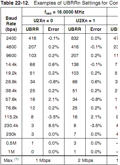
In that chart you'll see an error percentage. It depends on your external hardware, but generally don't count on your UART working at that baud rate if error is above about ~3%. It has to do with rounding errors, but lets not get into details . . .
Selecting The Capacitors
Search around, and in the datasheet you'll see something like:
"Low Power Crystal Oscillator Operating Modes".
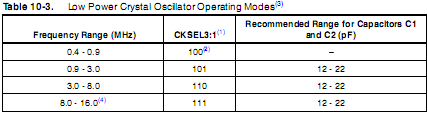
Now in this chat you'll see two important things. On the left is the frequency you want, which for most cases you want to be as fast as possible. Lets assume 16MHz and that UART error is acceptable for you.
Now on the right is a table that matches frequency with acceptable crystal capacitance. Thats right, you'll need two capacitors that match up to your crystal. It'll say something like 'Recommended Range for Capacitors C1 and C2 (pF) 12 - 22'. This means you can use any capacitor from 12-22pF.
Selecting The Crystal
Now go to your favorite online parts store, like mouser.com or digikey.com. Search for
crystals. You'll get an option that says 'Load Capacitance'. The load capacitors
on your circuit must be ~2x this value.
Lets say the traces and other stuff on your PCB causes an already existant capacitance of 3pF (typical). And lets say the crystal specifies a load capacitance of 12pF. Then use this equation:
(load capacitance - PCB capacitance) * 2 = crystal capacitors
or
(12pF - 3pF) * 2 = 18pF
Remember, this capacitance has to be within range of the value in the microcontroller datasheet.
Then select for Tolerance and Frequency Stability as whatever you want. The Frequency Tolerance of an oscillator is defined as the initial deviation of the oscillator frequency as compared to the absolute at 25C. The Frequency Stability over temp is defined as the frequency deviation compared to the measured frequency at 25C over the defined operating temperature range (ie 0C to +70C). Stability tolerance is sometimes expressed as a percentage of frequency deviation rather than as Parts Per Million (PPM) The conversion is as follows:
0.01 % = 100 PPM
0.005 % = 50 PPM
0.001 % = 10 PPM
The stability tolerance of a oscillator needs to be specified, along with the operating temperature range. For instance, a crystal may be specified as having a frequency stability tolerance of 50 PPM over an operating temperature of -45C to + 85C, and having a frequency tolerance of 50 PPM at +25C.
Anyway, now that you know you need 18pF capacitors, go buy two small ceramic caps as well.
Wiring the Circuit
Now open up your microcontroller datasheet once more and look for the pinout. You'll
see something like XTAL1 and XTAL2. Wire it all up as shown in this schematic:
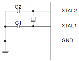
Make sure the caps are super close to the crystal, and the crystal super close to the microcontroller. This is so to reduce electrical noise and internal capacitance that could mess up your clock.
Changing the Fuses
Now that the hardware is done, you need to change the clock fuse settings on your microcontroller.
Now be VERY careful, if you mess this up, you'll probably brick your microcontroller (meaning you need
to buy a new one).
Go to AVR Studio or whatever software you use to program fuses. For the Axon, it'll look like this:
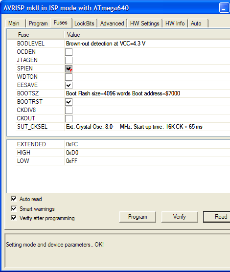
Make sure its 'Ext. Crystal Osc.'. Don't worry about not defining the speed, the crystal does that. The start up time can be whatever, but I prefer making it slow for my applications.
Oh, and in your software, don't forget that since your clock is much faster, you'll have to reprogram stuff like for your servo PWM.
Anyway, enjoy your souped up microcontroller!
Society of Robots copyright 2005-2014