
 Search Here
MISC
Parts List
Robot Forum
Chat
Member Pages
Axon MCU
Robot Books
Shop
Contact
SKILLS
How To Build
A Robot
Tutorial
Calculators
Mechanics
Programming
Miscellaneous
Robots
Space
HARDWARE
Actuators
Batteries
Electronics
Materials
Microcontrollers
Sensors
SCIENCE
Robot Journals
Robot Theory
Conferences
The H-Bridge is the link between digital circuitry and mechanical action. The computer sends out binary commands, and high powered actuators do stuff. Most often H-bridges are used to control rotational direction of DC motors. And unless you buy a potentially expensive motor-driver, you need an H-bridge to control any robot with a motor.
This is a quickly sketched H-Bridge circuit with supporting circuitry.
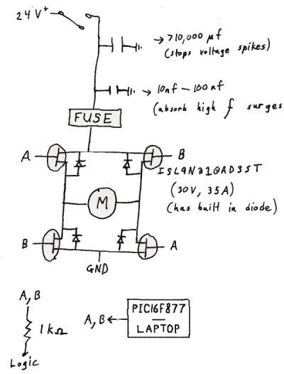
Use PNP transistors for the top two MOSFETs, and NPN MOSFETs for the bottom two (the ones connected to ground). Otherwise bad stuff could happen.
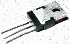
First lets talk about what a transistor is. These nifty chips revolutionized the electronics industry and you would be hardpressed to find something electronic that does not have at least a few thousand of these in them. So what do they do? They can control a flow of electrons by applying a voltage to them. The plumbing equivalent would be a water valve. By rotating the valve, a very large flow of water can easily be controlled.
There are several types of transistors, such as the PNP and NPN, but
for sake of making your life easy I will only talk about a
MOSFET
(Metal-Oxide Semiconductor Field Effect Transistor). These neat things
have only been around for a decade or two, but are way better than
the more traditional transistor. First they are more efficient. They are
easier to calculate mathwise. Plus they usually have built in
protection diodes so you don't need to add them in later. They even have
PWM (explained later) optimized MOSFET's.
So to operate a MOSFET, you apply a voltage to the gate (from your microcontroller), and suddenly a current of electrons passes through the other two pins. Connect a motor (M) in line with one of the pins and your robot is set to go. In the above schematic you will notice the letters A and B. These are your two control lines which you apply this logic voltage to. Since you have two pins, and only a binary control, there are four possible things that can happen.
A=0 B=0 : Nothing happens, the motor is turned off
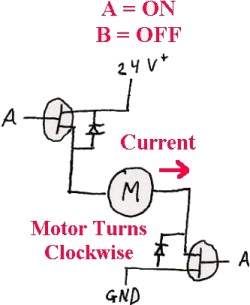
A=1 B=0 : Motor rotates clockwise
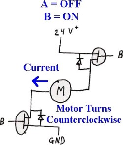
A=0 B=1 : Motor rotates counterclockwise
A=1 B=1 : Your circuit explodes into pretty sparks
Here is a ghetto visual graphic of the H-bridge logic chart:
So now lets talk about how to operate the MOSFET's. Basically all you need to do is attach the gate to your digital output of your controller. When the digital output is turned on, 5V will be applied to the gate, turning the MOSFET on. However it is better to amplify that 5V to a value higher and I will explain why. The gate voltage controls the MOSFET internal resistance. Zero voltage makes the resistance too high for it to work. A very high voltage has a very low resistance. Resistance leads to loss of energy thermally. This means your MOSFET will heat up and possibly burn out. Take a look at the MOSFET picture above and you will notice my finger print in it. That is what happens when you touch a hot MOSFET - pain! So although you do not need to amplify the gate voltage, it is best to do so. You should also put a heat sink on it.
Ok so what if you want speed control, and not just an on/off switch? PWM!
Pulse width modulation. PWM is when you send a square wave at a certain frequency
to control the MOSFET as shown above. Basically you are telling your controller to turn on and off the motor at very high
rates. So through inductance the motor is neither fully on or fully off, but somewhere
in between. Such as at a slower speed. Also a note that motor torque, under PWM,
remains the same whether fully on or only a percentage on. However, varying voltage for
speed control reduces torque. So with PWM you have maximum torque yet slower speeds!
You will have to experiment with wave length for both on and off periods,
as well as frequency, to optimize your speed control. But a guess usually works.
Make sure the MOSFET you have has built in protection diodes. If not, install them on your circuit as shown. This is to prevent back currents from your DC motor. Also do not forget to put a small capacitor across the leads on your motor to reduce electronic noise and increase motor life. You might also want to refer to the tutorial on robot power regulation to help you design a better power source for your H-bridge.
It is also recommended to put a slow blow fuse after the power supply, resistors of a few 100 ohms on the gate logic, and the additional capacitors on your circuit as shown. This will prevent melting, large voltage surges, and high frequency emission.
Society of Robots copyright 2005-2014