
 Search Here
MISC
Parts List
Robot Forum
Chat
Member Pages
Axon MCU
Robot Books
Shop
Contact
SKILLS
How To Build
A Robot
Tutorial
Calculators
Mechanics
Programming
Miscellaneous
Robots
Space
HARDWARE
Actuators
Batteries
Electronics
Materials
Microcontrollers
Sensors
SCIENCE
Robot Journals
Robot Theory
Conferences
- Shock loading (sudden short term forces)
- Dynamic influences (momentum)
- Off centre distribution of force
- The possibility of an overload weight/torque
- Strain Gauge Fatigue (constant use and wear)
- Cable Entry Fatigue (the output wire bending a lot)


(images: left 6 detect force, right 5 detect torque)
Force Sensors (Force Transducers)
There are many types of force sensors, usually referred to as torque cells (to measure torque)
and load cells (to measure force). From this point on I will refer to them as
'force transducers.'
Force transducers are devices useful in directly measuring torques and forces within your
mechanical system. In order to get the most benefit from a
force transducer, you must have a basic understanding of the technology, construction,
and operation of this unique device.
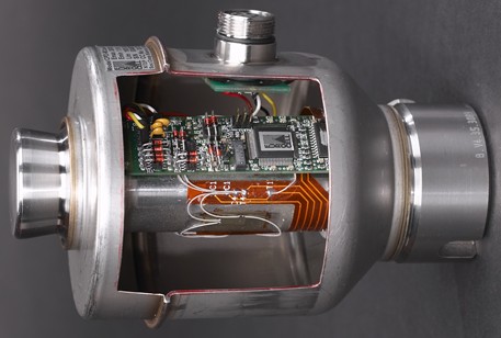
Digital Load Cell Cutaway
Theory of Measuring Forces
There are many reasons why you would need to directly measure forces for your robot. Parameter optimization, force quantitization, and weight measurement are a few. You may want to put force transducers on your bipedal robot to know how much weight is on each leg at any point in time. You may want to put force transducers in your robot grippers to control gripper friction - so as to not crush or drop anything picked up. Or you could use it so that your robot knows it has reached its maximum carrying weight (or even determine how much weight it is carrying).
First, I will talk about how a force transducer converts this force into a
measurable electrical signal.
Strain Gauge
(please note that compression and tension are mislabled, and should be swapped in the below animation - sorry!)
Note that the wire colors are usually red, black, green, and white, and that some
manufacturers for some lame reason use the red and black wires for signal and not for power.
You will probably need to further amplify the signal a factor of another few thousand, but
that can easily be done with a voltage difference amplifier.
Your output will give you a negative voltage for one direction of force, and a positive
voltage for the opposite direction. If you are measuring voltage with an oscilliscope or multimeter,
this is easy to measure. But for a microcontroller,
you cannot have any negative voltage output. A microcontroller can only read 0V to 5V. As a solution,
use a 2.5V voltage regulator for ground of
your force transducer, and a 7.5V ~ 8V voltage regulator for power to your force transducer. This will
effectively shift the output voltage to 2.5V neutral output to your microcontroller. Your range
should be between 0 and 5V. To limit your sensor within that range, experiment with your amplifier
gain.
Costs
Don't make your choice on sensors based solely on price - cost of ownership
is more important too. Maintenance costs, recalibration time, possibility of failure, etc should all be factors.
As a side comment, there are ways to make your own
force transducers if your too poor, but that is outside of the scope of this tutorial.
So if you think buying a force transducer is for you, continue reading.
The measuring range is the range of values of mass for which the result of
measurement is not affected by outer limit error.
The safe load/torque limit is the maximum load/torque that can be applied without
producing a permanent shift in the performance characteristics beyond specified.
The safe side load is the maximum load that can act 90 degrees to the axis along which
the transducer is designed to be loaded at without producing a permanent shift in the
performance beyond specified.
A force transducer will perform within specifications until the safe
load/torque limit or safe side load limit is passed. Beyond this
point, even for a very short period of time, the transducer
will be permanently damaged.
Capacity Selection, Derating
Damage
Lightning
Moisture
Corrosion
Extras
You may also be interested in the data logging
tutorial so that you can log your force/torque sensor data effectively.

The strain gauge is a tiny flat coil of conductive wire
(ultra-thin heat-treated metallic foil chemically bonded to a thin dielectric layer blah blah blah)
that changes its resistance
when you bend it. The idea is to place the strain gauge on a beam (with a special adhesive), bend the beam,
then measure the change in resistance to determine the strain. Note that strain is directly
related to the force applied to bend the beam. Unfortunately strain gauges are somewhat
expensive at about $10-20 each, usually coming in packs of 5-10 (so its like $50-$100).
If you are willing to experiment, and your forces are small, you can also use
conductive foam as a strain gauge. Compressing the foam lowers the electrical resistance.
If you want more details, see this strain gauge tutorial.

Wheatstone Bridge
The typical strain gauge has a VERY LOW change in resistance when bent. So to measure
this change in resistance, several tricks are applied. There is a ton of theory on this
so I wont go into how it works, but basically a neat circuit invented in the 1800's can
be used to easily amplify this difference. These circuits are built into all load and
torque sensors so you do not need to be concerned with how they work, just how to use them.
The strain gages inside the force transducer, usually a multiple of four, are connected into a Wheatstone
bridge configuration in order to convert the very small change in resistance into a usable
electrical signal. Passive components such as resistors and
temperature dependent wires are used to compensate and calibrate the bridge output signal.
Anyway, most force transducers have four wires coming out of them, so all you need to do
is attach them as prescribed here:


Unfortunately force transducers are on the expensive side. Expect to spend
between a few hundred to a few thousand dollars each. There are many different
types of sensors, of different dimensions and capacities and qualities, from
a large variety of companies. Check the ad window on the top right of this
page for several force transducer companies. Know that some companies hire
actual engineers for tech support, some don't. Actual conversation
I once had: "I have some technical questions, are you an engineer?"
"Ummm, I don't have a degree in engineering, if that is what you mean. But I think I can
help you." Surprisingly, some companies do not actually include a spec sheet
(Certificate of Calibration) with their sensor, so you have no idea what
the voltage-torque curve is! Insist on getting one, or expect to spend hours
testing and graphing when you get your sensor.

Capacity Selection
Force overload is the primary reason for transducer failure,
although the process of selecting the right force capacity
looks easy and straight forward. There are several terms you must understand
to properly select for load capacity:
Unfortunately you cannot just rate your transducer by
static forces alone.
There are many additional issues you must be concerned about:
If there is a possibility that any of these may occur, you must then derate
your force sensor (use a higher capacity). For example, if you
expect a high fatigue rate, you should multiply your required capacity
by two. Make sure you understand what you are measuring so that you do not
waste money on a soon-to-be-broken force transducer. Over time, you may want to
recalibrate your sensor occasionally in case of long term fatigue damage.

Because force transducers are expensive, preventing them from being
damaged should be a high priority. There are many ways to damage
a transducer. Shock, overloading, lightning strikes or heavy surges in
current, chemical or moisture ingress, mishandling
(dropping, pulling on cable, etc.),
vibration, seismic events, or internal component
malfunctioning to name a few.
If your sensor becomes damaged, don't just re-calibrate it.
Mechanical failure may have catastrophic effects and you
will no longer have a reliable sensor.

"Investigations indicate that a lightning strike within a
900ft radius of the geometrical centre of the site will
definitely have a detrimental effect on the weighbridge."
In most cases, the actual damage is a direct result of
a potential difference (1000+ volts) between the sensor circuit and sensor housing.
If lighting strikes commonly happen near your area,
make all grounds on your circuit common so the voltage floats together -
and use surge protectors! And of course, no electric welding should be
done near your sensor (hey, it has happened).

Obviously, water and electronics do not mix. Force transducers
are always sealed to keep out the elements, however moisture/condensation
damage occurs from a slow seeping over a long period of time.
The damage can be multiplied when acids or alkalines are present.
The most likely entry area for moisture is at the cable entry point,
so it is important to keep this area protected more than any other.
Manufactures employ many techniques to seal it off, but there are additional
techniques you the user can also employ. Know that often temperature changes
can cause a pumping action to
occur, pushing moisture down the inside of the
cable. Entry also can be via a leaking junction box or through
a damaged part of the cable. This can take some time to reach
critical areas, but once there it will become sealed in place and
do critical damage.

The effects of corrosion on your force transducer will be the result
of both the manufacturing quality and the environment in which the sensor is used.
Make sure you understand how likely your choice in transducer
is likely to corrode over time. Consider the metal type of the outer
casing, the surface finish, the weld areas, thickness/quality of moisture seals,
and cable material (PVC, PUR, or teflon).
Also understand the environment - salt water, for
example, has different corrosion effects depending on the local
circumstances. Stainless steel in stagnant salt water is subject
to crevice corrosion (a regular wash down is necessary to
avoid degradation).
Don't assume stainless steel means "no corrosion, no problem and no maintenance".
In certain applications, painted or plated load cells may offer better long-term
protection.
An alternative is wrap-around protective covers. These can
provide good environmental protection, but can be self destructive
if corrosive material is trapped inside the cover.
Sealing compounds and rubbers used on some transducers can deteriorate
when exposed to chemicals or direct sunlight. Because
they embrittle rubber, chlorine-based compounds are a particular problem.
Always make sure you keep your sensor maintained and clean to avoid corrosion.
Installation
There are several considerations that are often forgotten during the mounting
of force transducers. For example, it is a common misconception
that a force transducer can be considered as a solid piece of metal on which
other parts can be mounted. The performance of
a force transducer depends primarily on its ability to deflect repeatably
under conditions when load/torque is applied or removed. Make sure
all supports are designed to avoid lateral forces, bending moments,
torsion moments, off center loading, and vibration.
These effects not only compromise the performance of
your force transducer, but they can also lead to permanent damage. Also,
consider self aligning mounts.

The S-Beam Load Cell Changes Shape Under Load
Force Transducer Cables
Special attention should be paid in preventing the transducer
cable from being damaged during and after installation. Never
carry transducers at their cables and provide dripping loops to
prevent water from running directly into the cable entry.
Don't forget to provide adequate protection for the
cable, near the sensor if possible.
Load cells are always produced with a four- or six-wire cable. A
four-wire cable is calibrated and temperature
compensated with a certain length of cable. The
performance of the load cell, in terms of temperature
stability, will be compromised if the cable is cut; never cut
a four-wire load cell cable! 6 wire cables can be cut, but all
wires must be cut evenly to avoid any differences.
What I have talked about is actually a very watered down tutorial for
force transducers. If you would like to learn more, read the
advanced load cell tutorial.
I didn't write it, so good luck!
Society of Robots copyright 2005-2014