
 Search Here
MISC
Parts List
Robot Forum
Chat
Member Pages
Axon MCU
Robot Books
Shop
Contact
SKILLS
How To Build
A Robot
Tutorial
Calculators
Mechanics
Programming
Miscellaneous
Robots
Space
HARDWARE
Actuators
Batteries
Electronics
Materials
Microcontrollers
Sensors
SCIENCE
Robot Journals
Robot Theory
Conferences
STEP-BY-STEP ROBOT TUTORIAL
STEP 3a: CONSTRUCT THE CONTROLLER
Electronics
In step 3 of the step-by-step robot tutorial we will now build the brains
(electronics systems) of our robot.
This step should take you about three to four hours from start to completion.
There are three major electronic systems for all robots, and you will build each of these in this tutorial:
1) Power Regulation - this system ensures your robot always gets enough power and the correct voltages to run all other systems without interruption.
2) Microcontroller - this is the actual brain of your robot. It is the device you program, and controls all other systems of your robot. For your robot, you will be using the AVR ATmega8 (the big black chip with all the pins sticking out of it).
3) Sensors and Actuators - for any control system you need both a sensor for the robot to 'see' the world, but also actuators to react to what it sees.
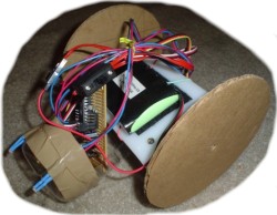
Transistioning between mechanical construction and electronics, we need to setup the batteries. There are two ways I will show you how to do this. The first way I will show you, and also the better yet more expensive method, is by using a 6V RC battery pack. This is the same battery pack I used in Step 2 to test as a remote control robot.

You can probably locate a pack like this from a remote control car you own, buy online for ~$10, or make your own by putting 5 AA batteries in series. For small robots I recommend NiHM type batteries at 1500mAh and above. If you are serious about robotics, put in the money and buy a battery pack! Its a good investment (I own like 4 of this type of battery, not including all the other types I got).
You should also consider getting an ON/OFF switch for your battery pack, although it isnt really required (you could just unplug your battery). I got this one for ~$2. Plug your battery into one end, and the other end can go to the battery connection on your robot. Also, notice the velcro on the bottom of the battery. I will talk about this in the following section.

Now just place the battery pack on the velcro already on your robot. You could also use long cable ties or tape, but I don't recommend it. What I like about the water bottle on the robot is that I can put stuff into it - batteries, sensors, baby squirrels, etc. You could also mount a small box on top of your robot to store the batteries. As a matter of fact, the Olimex programmer you bought for this project comes in a box that is just the right size. You are only limited by your imagination and what you have available to scrap.

And you're done! (with batteries)
For more battery information, check out the batteries tutorial.
But suppose you don't have the money or don't want to buy a battery pack. There is another way.
The other battery method is to get a battery holder, use the AA's that you have in your digital camera to power servos, and a 9V battery to power the AVR microcontroller.
These are three different types of battery holders I own, but the middle one is best because its encased and has a built-in ON/OFF switch. All three can be bought from RadioShack (buy the middle one!!!).

Opening the battery holder up, I put four AA NiMH type batteries into it. Make sure you use rechargeable batteries, as they last much longer and supply much better power to your robot servos (thereby making Al Gore happy). You need four batteries.
If you dont own AA batteries (cause you're weird or something), you can buy them for like $5 at any convenience store. Get the ones with the highest number for mAh and that say NiMH. Buy a charger if you don't already own one, too - or continue reading later on how to make your own battery charger. I assume you have batteries already cause most people own a digital camera (so I didnt include it in the $50).

I like to use velcro to attach batteries to small and medium sized robots. This allows me to easily remove batteries for recharging, or to quickly put on other robots I've made that share the same battery pack.
Cut a small sheet of velcro into a square as shown.

Remove the protective backing from the velcro and stick the velcro on to the bottom of your battery pack. I realize at least one person out there is going to make the dumb mistake of covering up the screw with the velcro - don't do that! =P

Then just simply attach the velcro to the velcro already on the robot.

If you don't have velcro, you can also drill a small hole inside the plastic, and put a screw through it. Then drill another hole in your robot, and pass the same screw through that hole too. Lastly, use a nut to tighten the screw on.
This is a demonstration of me doing it, although I didn't actually drill a hole (pretend, please!).

If you plan to build many robots in the future, I recommend going out to buy a 25 foot roll of velcro for like ~$20. I use it all the time for attaching batteries, and it will last you like 5+ years. Definitely a good investment.
Before we continue, I want to show you a cheap way to recharge your batteries. Search around for a power supply in your house that you are no longer using. They are fairly easy to find and/or scrap.

Make sure it outputs the same voltage as your batteries. For example, if you have a 6V RC battery pack, make sure the power supply says 6V. If you put four battery cells together, make sure it says 4.8V (because 4 cells at 1.2V each equals 4.8V). Make sure it outputs a low current (trickle charge). 100mA seems to work fine for me. If the output current is too high, your batteries could overheat and as a consequence become damaged (or start a fire).
Typical recharge times will be about 10+ hours. The more professional chargers out there that you can buy could take significantly less time, as they are designed to charge as fast as possible without damaging the battery. These chargers range from $10 to $60, dependent on features.

Now cut off the adaptor end of the long wire. There are two ways you can attach it to your battery. You could use aligator clips to connect the power supply to your battery pack wires (make sure ground and power aren't reversed). The method I used is to attach a male header to the wires so it goes right into the RC pack plug. I will talk more about male headers towards the end of this page.
Now lets go over the components you will need for your first robot. If you would like to learn more about basic electronics, have a look at the electronics basics tutorial.
This is a 5 pack of photoresistors I bought from RadioShack. This variety is great, cause now I can choose the 2 photoresistors I like best (aka, give the best sensor readings). For more information on photoresistors, read the photoresistor tutorial.

This is a prototyping board (known by RadioShack as a 'Component PC Board,' wherever they got that from . . .). To use it, stick your components into the board and solder them in according to the schematic, as I will soon show. These boards are also known as 'perf boards', short for perforated boards (has lots of holes in it).

You can also get what is called a breadboard. It works in a similar way to a prototyping board, but none of the connections are permanent. The benefits are that it doesn't require any soldering, and that you can quickly change your circuit as you please (great for experimenting!). The one shown here is a mini-breadboard, small enough to fit on your robot, and it has a sticky backing that you can stick right on to your robot with no effort.

There are two disadvantages to the breadboard: they can be a little costly, and the connections aren't as secure as with a prototyping board. I wont be using the mini-bread board for this project, but if you plan to build more robots in the future, I suggest you to make an investment =P
These are the parts I got from the DigiKey Order. Note the two grayish bags labeled 'Static Shielding Bag' on the bright yellow warning labels. This basically means that the components inside these bags are static sensitive, so be careful. Keep these bags, as they could be useful for your future electronics projects, or at least a good storage place for sensitive electronics.

Your battery is never a fixed voltage. Just because it says 6V doesn't mean it couldn't be 7V or 5V. This voltage always changes, and can cause havoc on your microcontroller and sensors. To correct for this, you need a 5V voltage regulator. What this does is ensures 5V will always be supplied to your sensitive electronics.
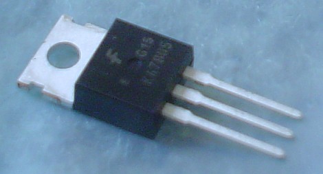
The voltage regulator will have three pins: Unregulated Input, Ground, and Regulated output.
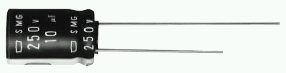
The large capacitor is not entirely necessary, but is good to help reduce electric noise and keep the system powered during sudden power drains. Even a short lived sudden drop in power could reset your robot microcontroller (bad). The value of this capacitor doesn't really matter, but 100uF and above is a good starting point. More servos you use, the higher you want it to be. It should also always be rated twice that of your input voltage. Your input voltage is ~6V, so you would want it rated for 10V or 15V.
A second 0.1uF capacitor must go between GND and AVCC, as close to the microcontroller pins as you can make it. This capacitor is required to create a low pass filter for the analog-to-digital (ADC) converter.
If you ever do high precision ADC measurements (unlikely), put a 0.1 uF cap in between AREF and ground as well. The point behind having the AREF pin is so you can feed it an input from a super-stable voltage source, and it will scale the ADC inputs from ground up to AREF with the full 10 bits of precision. Of course, you need to make sure none of your analog inputs go over AREF if you are using it like that.

The LED will be used as a status indicator. The LED is useful for knowing if your microcontroller is powered properly, and can output other useful information for testing purposes. A resistor wired in series is required so keep the LED from frying. Any resistor value from 10 ohm to 1 kohm will probably work. Higher resistance values reduce the power drain (good), but also decrease brightness (bad).
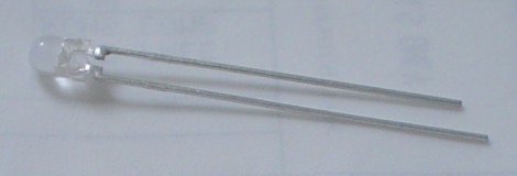
Note that the two wires on the LED are different lengths. The longer wire is always + and the shorter is -. The LED is polarized, meaning they will only work if current goes the correct way. If you connect it in reverse, they will either fry, or just simply not work.
The long black thing with pointy metal pins sticking out of it is called a male breakaway header. These things, useful for plugging in servos and sensors, can be easily broken to your custom length requirements.
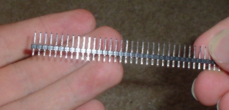
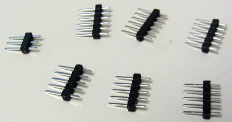
To break them, you can either use your hands, or a pair of sharp snips or scissors also works. Break three of length 6, five of length 5, and one of length 3.
Click to continue to Step 3B >>>.
This part will involve soldering of components to the perf board.
Society of Robots copyright 2005-2014