
 Search Here
MISC
Parts List
Robot Forum
Chat
Member Pages
Axon MCU
Robot Books
Shop
Contact
SKILLS
How To Build
A Robot
Tutorial
Calculators
Mechanics
Programming
Miscellaneous
Robots
Space
HARDWARE
Actuators
Batteries
Electronics
Materials
Microcontrollers
Sensors
SCIENCE
Robot Journals
Robot Theory
Conferences

Setting Up Hardware
Part #1: Installing Software
Part #2: Setting up Hardware
Part #3: Using the Bootloader
STEP 1: Install USB Drivers
To use the USB for the first time you must first install the USB driver file. Simply download the .exe file appropriate for your operating system and install it.
Next, plug in your USB cable (you do not need to power the Axon to do this).
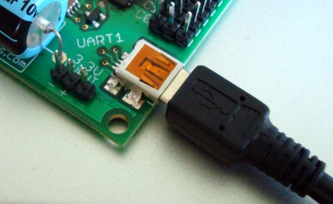
Your computer should now detect the new hardware and ask you about drivers for the CP2102 (the USB converter chip on the Axon). Follow the installer directions given until complete.
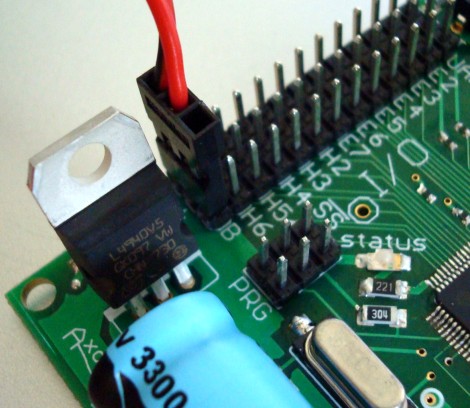
STEP 2: Connect Power
Now you must plug in your battery. Look for the pin labeled 'B' or 'Bat' on your Axon at the bottom left side. The middle pin is for power, and the left pin is for ground.
A 6V NiMh battery with Hitec connector is recommended, but you can also use 7.2V and/or a NiCad battery type. Be aware that some servos may over heat at greater than 6V.
See the Axon datasheet for more info on voltage/current tolerances.
The Hitec battery connector has three wires, one for the battery, one for the Axon, and one for a battery charger. This lets you embed the battery in your robot without having to open it up to charge your robot or turn it on.
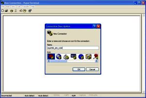
STEP 3: Test USB
Download this hyperterminal config file, then double click it.
For instructions on configuring it correctly, check out my hyperterminal tutorial.
Select your COM port and baud rate (115.2kbps), then click connect. You should immediately start seeing data.
Remember, if your receiving junk data, that means you improperly set up the baud rate but everything else is working fine. It also means you should read the FAQ on UART gibberish.
If you don't like HyperTerminal, another popular terminal program to try is Tera Term.
note: The first 15 Axons shipped in 2009 had an incorrect baud rate pre-installed on the factory installed test program. Nothing major, but if you want to test the USB before programming the Axon (not required), simply bootload up the newest test program to overwrite the old one.
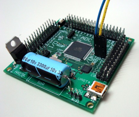
STEP 4: Connect Sensors & Servos
Servos can be connected to any header on the left and right of the Axon. Ground (black wire) is always the outside row, and red (power) is always the center row.
Analog sensors, such as the Sharp IR Rangefinder should always be connected to the regulated 5V bus. The 5V bus is the first 16 (ADC #0-15) headers on the top header row of the Axon.
An example:
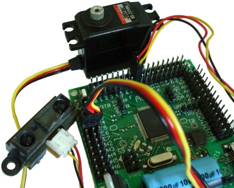
You can also take power from the Axon for other external devices as shown with the red and black connector on the left:
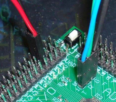
A UART connection is demonstrated on the right.
STEP 5: Connect UART
The UART is a way for the Axon to communicate with other hardware through serial, such as a camera, bluetooth, or GPS. It's as easy as plug and play.
T is for transmit, R is for receive, and G is for ground (make sure external devices share a common ground!).
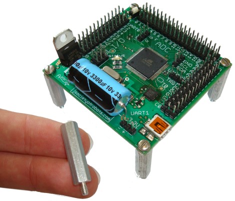
STEP 6: Mount Axon to Robot
It is recommended to mount your Axon to your robot using spacers at least .25" long. Here is an example with 1" spacers and four screws (not included):
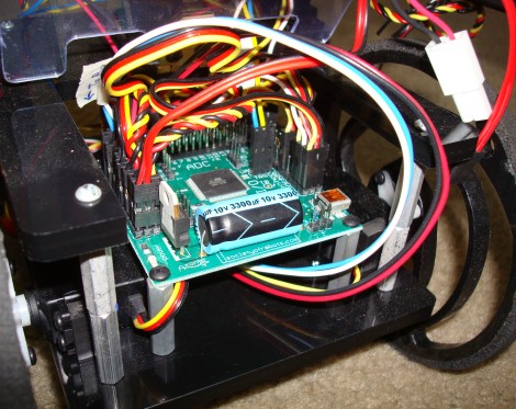
Here is an example of it mounted to the ERP:
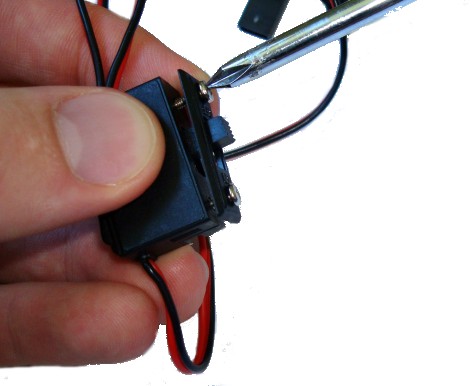
STEP 7: Mount the On/Off Switch
The included on/off switch has a plate that can be removed to help you mount it to your robot in an easy to reach location.
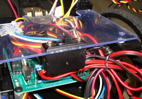
Here is an example of it mounted to the ERP:
Now that you are done setting up hardware, continue to
Part #3: Using the Bootloader >>>
Society of Robots copyright 2005-2014