
 Search Here
MISC
Parts List
Robot Forum
Chat
Member Pages
Axon MCU
Robot Books
Shop
Contact
SKILLS
How To Build
A Robot
Tutorial
Calculators
Mechanics
Programming
Miscellaneous
Robots
Space
HARDWARE
Actuators
Batteries
Electronics
Materials
Microcontrollers
Sensors
SCIENCE
Robot Journals
Robot Theory
Conferences
TUTORIAL FOR ROBOTS
|
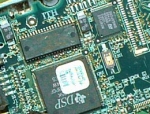
Electronics can at first seem extremely complicated to understand and learn. One look at a circuit board with all those little blinky LED's and black chips and unidentifiable circle pointy things can make anyone quit before starting.
But actually electronics can be much simpler than you think. Learning electronics is more like learning a foreign language alphabet. At first glance it is all a bunch of squiggles. But actually each letter has its own pronounciation and its own rules of use. And certain combinations of letters in a certain order form a word of some meaning. And a combination of words forms a sentence. This is the same for a circuit board. Each tiny component, such as a resistor or capacitor or transistor, has special rules and abilities. Combining a few into a circuit can create interesting effects. Combine a bunch of unrelated circuits together and suddenly you have a robot. So your first step would just to be to learn and understand the smallest of the components. Once there you can learn about combining them. Just like learning a foreign alphabet, no?
Ok first a quick crash course in electron physics.
All electronics is designed to manipulate a flow of electrons. Electrons have mass
and volume so you can almost think of electrons in circuits as
water flowing through plumbing. The analogy is amazingly helpful if you think about it.
Also note, the more electrons you have in one place, the higher the voltage. The more
electrons moving together, the higher the current. The same as with water.
Ground and Source
Now think of this as water.
Water flows down the easiest quickest path between these two points. More resistance to flow,
less will flow.
The last point is important as it is the basis of Ohm's law, V=IR.
Voltage = Current x Resistance. For example, suppose you take a resistor
and connect the two ends of a battery with it. You know that your battery is 9V (or whatever)
and you know the resistor is 3Kohm (determined by the color stripes on the resistor),
so 9V divided by 3Kohm is .003amps (3 milliamps). So why is this information useful?
Well now that you know the current, you can determine other useful things such
as power. P=IV. You will notice that if you increase resistance, you decrease current.
If you decrease current, you decrease power use. Put a 1ohm resistor between
the battery and it will get so hot it could burn because of the power use. Use a 100Kohm
resistor and almost no power at all will be used.
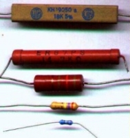
So about determining the value of a resistor, all resistors have the value labled on
them. You will notice colored stripes on the resistor. Each stripe means a certain number.
This has been explained a billion times online already so I won't, just google search
'resistor color tutorial.'
Quick note, some capacitors are polarized, meaning current can only flow one direction
through them. If a capacitor has a lead that is longer than the other, assume the longer lead
must always connect to positive.
How do capicitors charge over time? This Capacitor Charge Curve Chart should help. The discharge
rate would be the direct inverse. Theoretically (as made obvious by the graph)
a capacitor can never be fully charged or discharged,
but in reality this is never the case.
So how can you use capacitors in your robot?
Power surge/drainage management.
The problem with using robot components that drain a large
amount of power is sometimes your battery cannot handle the high drain rate. Motors and servos being perfect
examples. This would cause a system wide voltage drop, often reseting your microcontroller,
or at least causing it to not work properly. Just a side note, it is bad to use the same
power source for both your control circuitry and your motors. So don't do it.
Or suppose your robot motors are not operating at it's full
potential because the battery cannot supply enough current, the capacitor will make up for it.
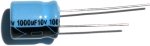
The solution is to place a large electrolytic capacitor
between the source and ground of your power source. Get a capacitor that is rated at least twice the voltage
you expect to go through it. Have it rated at 1uF-10uF for every amp required. For example, if your 20V motors will use
3 amps, use a 3uF-30uF 50V rated capacitor. Exactly how much will depend on how
often you expect your motor to change speed and direction, as well as momentum of what
you are actuating. Just note that if your capacitor is too large,
it make take a long time to charge up when you first turn your robot on. If it is too small, it
will drain of electrons and your circuit will be left with a deficit. It is also bad
to allow a large capacitor to remain fully charged when you turn off your robot.
Things could accidently short and fry, such as curious kitties that get too close. So use a simple power on
LED in your motor circuit to drain the capacitor after your robot is turned off. If your capacitor
is not rated properly for voltage, then can explode with smoke. Fortunately they do not overheat if given
excessive amounts of current. So just make sure your capacitor is rated higher than your highest expected.
Capacitors can also be used to prevent power spikes that could potentially fry circuitry. Next to any
on/off switch or anything that that could affect power suddenly should have a capacitor across it.
Capacitors can eliminate switch bouncing. When you flip a mechanical switch, the switch actually bounces several
times within a microsecond range. Normally this is too small of a time for anyone to care (or even notice), but note that
a microcontroller can take hundreds of readings in a single microsecond. So if your robot was counting the
number of times a switch is flipped, a single flip can count as dozens. So how do you stop this?
Use a small ceramic capacitor! Just experiment until you find the power capacitance value.
Capacitors can improve efficiency and longevity of electric motors up to 100%. Place a small ceramic
capacitor of like 10uF across the two leads of your motor. This works really well with el-cheap-o
motors. Not much effect with high-end expensive motors however.
These capacitors will also signficantly reduce EMI (Electro Magnetic Interference) and system noise too.
This below chart represents the current vs voltage curve typical of diodes. As you can see,
the current passing through a diode changes non-linearly as voltage changes linearly.
There is another special diode called a zener diode. With the water analogy, a
zener diode is like a dam, but with a pump at the bottom pumping water back to the top.
Zener diodes allow current to flow in reverse as well as forward. The forward voltage
is still around .7V, but there is a different reverse voltage of around negative ~2.3V.
You will probably never need to use a zener diode.
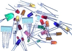
If you would like to learn more about the LED, check out my LED tutorial.
POWER
Power is simply the energy required to do something. If you are moving a large
amount of electrons, and moving them through something that is resistant of that movement,
power is used. Power is voltage times current. Power is also voltage squared divided by resistance.
P = I * V
P = (V^2)/R

Source is the positive part of your circuit. The plus end of your battery would go here.
Ground is the negative node of your circuit.
When you design your circuit, imagine a flow of electrons coming from the source, and heading to
the ground. A quick note, in reality electrons move from gound to source. The confusion has
historical reasons I dont want to get in to. But just know this fact, and pretend electrons
move from source to ground.
RESISTORS 
These do exactly what they say. They resist the flow of electrons. These are necessary for several
reasons:
- they can control how much current goes down each wire
- they can control power usage
- they can control voltages (since current, resistance, and voltage are interrelated)
Click for a quick resistor color code reference chart.

CAPACITORS 
Now suppose you want to control how the current in your circuit changes (or not changes)
over time. Now why would you? Well radio
signals require very fast current changes. Robot motors cause current fluctuations in your
circuit which you need to control. What do you do when batteries cannot supply current
as fast as you circuit drains them? How do you prevent sudden current spikes that
could fry your robot circuitry? The solution to this is capacitors.
Capacitors are somewhat complex in theory, but most people can get by on the basics which I will
explain here. Capacitors are like electron storage banks. If your circuit is running low,
it will deliver electrons to your circuit. If your circuit is in excess (such as when your
robot motors are turned off), it will store electrons. In our water analogy, think of this as
a water tank with water always flowing in, but with drainage valves opening and closing.
Since capacitors take time to charge, and time to discharge, they can also be used for timing
circuits. Timing circuits can be used to generate signals such as
PWM or
be used to turn on/off motors in solar powered BEAM robots.
DIODES 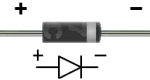
Diodes are what you would use to ensure current flows in only a single direction.
A great water analogy to a diode is a dam. Water never flows up a damn. But the
analogy goes even further. With diodes, there is always a voltage across it
(typically .7V forward voltage). Meaning if you have a diode come after a 7.2V battery,
the voltage would then be 6.5V. This is just like a dam in that the water level will always
drop. Doesnt current already always flow in only a single direction? No. RC circuits, or circuits involving
AC power, or circuits that are noisy (such as with motors),
involve currents that changes directions.
So why would you only want current to flow in a single direction? Many many reasons. But for a beginner,
you need to protect your circuitry from noise. A microcontroller would fry
if current went the wrong way. Motor drivers and MOSFETs would too. Diodes are also useful for dropping
high voltages to a lower more usable voltage.
Society of Robots copyright 2005-2014