 Search Here
MISC
Parts List
Robot Forum
Chat
Member Pages
Axon MCU
Robot Books
Shop
Contact
SKILLS
How To Build
A Robot
Tutorial
Calculators
Mechanics
Programming
Miscellaneous
Robots
Space
HARDWARE
Actuators
Batteries
Electronics
Materials
Microcontrollers
Sensors
SCIENCE
Robot Journals
Robot Theory
Conferences
What is IrDA?
IrDA, similar to UART, is a standard used for transmitting data by IR (infrared). The standard
is optimized based on various factors such as resistance to environmental noise, etc.
If you are interested in building and infrared transceiver, you need to have
a basic familiarity with the IrDA standard.
Chances are your IR transceiver will not be a single stand-alone device, and instead you will be using it for transmitting data from your microcontroller. I assume you will be using the available hardware UART on your microcontroller - please read that tutorial if you are not fully familiar with UART!
Before starting, check out my IR transceiver demo:
Infrared Transmission - The Wrong Way
Before we talk about the proper way to install an IR transceiver, I want to tell you about
the improper way. The improper way WILL work, however it will be much more susceptible
to noise, have a shorter range, and lower reliability.
In this inferior but simpler method, you would connect the UART Tx line to a resistor
and an IR LED. On the receiver end, you would connect the Rx to a phototransistor.
To get schematics and learn more, please check out my infrared emitter/detector tutorial.
And now for the proper way . . .
IrDA Transceiver
There are several ways to build an IR transceiver, but the method I recommend most is purchasing
an all-in-one IrDA package. It will handle the IrDA standard transmission for you and all you need
to do is connect power, ground, input, and output data lines.
There are several optical transceiver manufacturers, just go to your favorite parts
distributor site and look for 'IrDA [manufacturer name]' to find some:
Infineon
Agilent
Vishay/Temic
Rohm
The IR transceiver should handle all that low-level boring stuff, such as hardware handshaking, ID transmission, modulation, etc. If you want to know more, refer to the datasheets. This is not required knowledge so don't worry about it.
Also to note, the IrDA transceivers are 'half-duplex', meaning they can only transmit or receive, but not both simultaneously. You will need to have your microcontrollers coordinate data transfer (its actually pretty easy to do, I have confidence in you!).
IrDA Encoding and Decoding
The IrDA transceivers understand only IrDA standard signals.
The UART does NOT transmit IrDA standard signals, it transmits TTL. As a solution, you also need a TTL to IrDA encoder/decoder
converter.
How? Well, buy an IrDA encoder decoder IC, silly. There are many manufacturers of these IC's, but the one I used is the MCP2120 from Microchip.
There is another method other than using an IC to interpret the IrDA standard signals - you can emulate the conversion in software on your microcontroller. In fact, in industry, this is the preferred method because software is cheaper than hardware. If you don't need to save a buck, and/or don't know what you are doing, just go with the IC encoder method.
As with UART, you need to make sure all devices are operating at the same baud rate. Some devices have user selectable rates by applying voltages on various pins, and others have an auto-baud detect feature. Many of these devices also have reset pins to uuhhhh reset the hardware, and also enable/shutdown pins to put the devices into power-save mode. You also may need to install a clock - a square wave signal that times all the devices. The datasheet will explicitly state information on the clock, give a suggested schematic, and give you specs on the required external hardware (such as a crystal and capacitors). A clock can also be taken from a microcontroller (see microcontroller datasheet on clock oscillator info).
Everything Integrated
To help you better understand the system as a whole, this is the process by
which the signal takes:

where:
microcontroller => UART => IrDA encoder decoder IC => IrDA transceiver => infrared signal =>
IrDA transceiver => IrDA encoder decoder IC => UART => microcontroller
Now looking at just the left half, here is a closer breakdown on how things get wired up:

Of specific note, notice how Rx connects to Rx, and Tx connects to Tx. At first this seems confusing and counterintuitive compared to how UART is done. But actually, when a transceiver receives data, it also transmits it - so Rx is basically Tx. A bit confusing, but just follow the datasheets and this diagram to get the wiring correct.
This video shows how I soldered and assembled the transceiver.
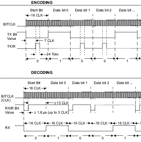
The IrDA to TTL Signal conversion
If you are curious how the IrDA signal looks after converted from TTL, see this chart:

Improving Range
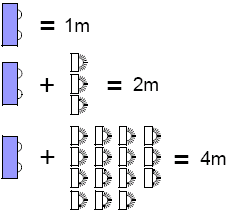
The IrDA standard calls for a transmission distance of
1 m, with the emitter and received mis-aligned up to
+/-15 degrees. But some applications require a greater distance.
This can be achieved with an increase in emitter
power, a lens for the receiver, or both. This below figure shows
how adding LEDs can be used to increase the transmission
distance.

As you can see, for every doubling of distance the emitter
power must be increased by a factor of 4.
For 4m distance, 15 LEDs would be need to be added in parallel.
Oh and few IR LEDs are fast enough for use in IrDA standard compatible applications.
The TON and TOFF for the LED device should be less than 100 ns.
Examples
Following are some images of my IrDA compatible transmitter. The first image is my schematic
using the MCP2120 IC:
This image is the transceiver wired up onto my custom PCB:
When its transmitting, you can see the pretty light by using a common digital camera. This is a very easy method to help you debug your hardware/software:
And this is an image of the encoder decoder IC on protoboard. I wasn't motivated to do it on a custom PCB since they offered a PDIP package for easy wiring:
And an image of the entire setup, consisting of my Axon microcontroller, a transceiver, and an encoder/decoder IC. The final data is being transmitted wirelessly by bluetooth to my laptop:
Further reading on IrDA and RS-232
http://www.maxim-ic.com/appnotes.cfm/appnote_number/3024
http://ww1.microchip.com/downloads/en/DeviceDoc/21618b.pdf
http://ww1.microchip.com/downloads/en/AppNotes/00756a.pdf
http://www.societyofrobots.com/robotforum/index.php?topic=4871.0
Society of Robots copyright 2005-2014