
 Search Here
MISC
Parts List
Robot Forum
Chat
Member Pages
Axon MCU
Robot Books
Shop
Contact
SKILLS
How To Build
A Robot
Tutorial
Calculators
Mechanics
Programming
Miscellaneous
Robots
Space
HARDWARE
Actuators
Batteries
Electronics
Materials
Microcontrollers
Sensors
SCIENCE
Robot Journals
Robot Theory
Conferences
- Use highly geared down servos - you want them to be really high strength. Actually over design your arms
and actuators to handle ~3x the expected maximum forces. Engineers like to calculate to optimize, but robots
need to be robust and handle the unexpected. Better to over design, because otherwise you will end up breaking
motors and having to redesign and buy new ones.
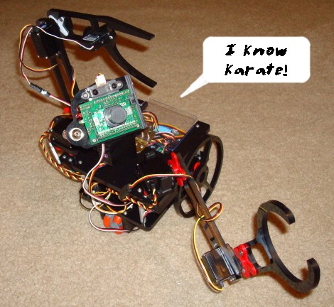
- Use a smoothed control algorithm. I know I know, ninja moves on a robot looks cool.
But ninja moves also break servos. You instead want slow Yoga like motions. And be especially careful
to slow the servo down to zero speed BEFORE the servo reaches it's full degree limit. I've broken three servos
from not doing that . . . I just assumed the internal servo electronics would do it for me, but nope! They
don't account for large swinging masses in the built-in control algorithms.
(Saturday May 31st, 2008) I posted ERP on instructables.com, and within an hour I got this email:
-
"Your Instructable 'Experimental Robot Platform' was just featured by one of our editors!
Look for it on the Instructables homepage within the next 30 minutes. Being featured means we think you are awesome. Keep up the great work!"
In addition to mechanical improvements, I also got the visual system up and running. I programmed it to track multiple colors, work in many different lighting conditions such as in a dark room or out in ultra-bright sunlight, and even track fire and a white line. Just watch the video:
All it basically does is do middle mass detection while filtering out the background by colors. Its all basic still, but I hope to get more advanced vision working in the coming months.
September, 2008: Better Arm and Gripper
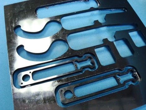
I constantly had the problem of my Hitec servos breaking below spec, and even melting, on my robot arm. Also, I decided that allowing the arm to flex was ok if it allowed the weight to be reduce another ~35%. So, I improved the robot arm design - nothing drastic, but the little things definitely added up. Here is a demo video of the latest arm. The gripper was designed so that it was simple to make, yet could pick up any object.My robots often get accused of being a kit I bought from some store (yeap, only aliens can make robots, not professional robotics engineers like me). So to prove its not a kit, here is a sheet of plastic after I used a CNC to cut out enough parts for two robot arms. I left in some of the parts for a good visual.
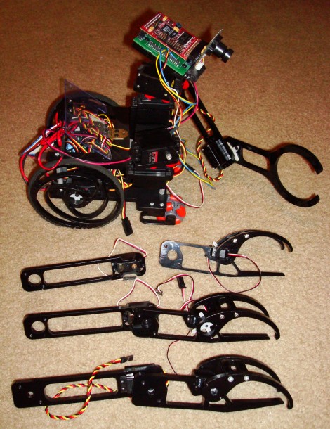
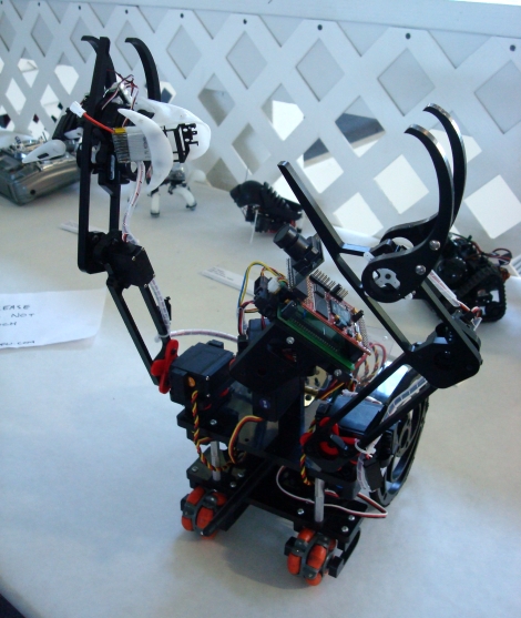
And here are three different versions of the robot arm next to my ERP. The oldest arm design is at the top. The first gripper design is at the bottom. The newest and final version are the two in the center. Notice how each new design is thinner than the previous. In the future I'll include video of both arms being used for something . . .
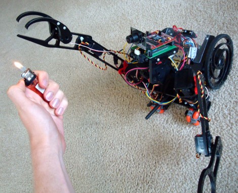
This was a very simple test to verify that my ERP was capable of grabbing and throwing a tennis ball. In no way did I optimize the throw, so I'm sure it can throw further after a bit of tweaking. No sensors were used in this test, although in the long term the camera will track the orange ball before grabbing it.
This video shows how I gathered up the wiring - the arms kept ripping out the servo wiring before I did this:
April, 2009: Biped Engine
You can't just hardcode positions to get perfect smooth motions in robot arms. A simple hardcode will result in a stop-start-stop-start jerky motion, making my ERP do the uhhhh . . . robot . . .An additional problem with jerky motions is that it tends to break servo gears, and cause power spikes that can potentially fry a motor driver board or cause a microcontroller reset.
So I installed my Biped Engine v2, and it works really darn well. I can program any set of required positions, define a speed, and the algorithm will linearly interpolate between each required position dependent on that speed.
This fun video shows it doing the same dance at four different speeds.
About the video
Chroma key was used to make one robot appear to be three. I actually filmed it three times, in three different locations, on a green floor, then combined the three together. If you look carefully, you'll see various chroma key artifacts that I didn't care to fix. I used Sony Vegas Movie Studioto make the video.
As for the background, I did all filming entirely in Thailand (where I often live for 6 months at a time). KMUTT supplied me the green floor and wall. The river pictures were from a recent trip I went on, and it just seemed to fit with my mood when I made the video . . .
June, 2009: Bluetooth & 3D Scanning
I added on remote control capability using bluetooth as shown in this tutorial video:This is a 3D scanning and mapping test for my ERP. Its basically mapping obstacles, then choosing the most free path. It scans in only 30 points, so its fairly poor resolution. It's only the first step for a more advanced algorithm in the future.
June, 2009: RoboGames 2009
I had taken ERP down to RoboGames 2009 in San Francisco to compete. I spent way more time socializing than getting ERP to work properly, but he still did pretty well. He got 1st in Table Top Nav and 2nd in Kinetic Art (results).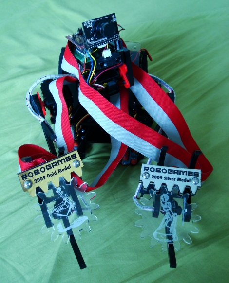
ERP also met some famous people and robots. First on the list is Lem from the popular robots in Japan blog, robots-dreams.com.
ERP also made some robot friends with Crabfu. He really thinks Swashbot is such a cute little bug.
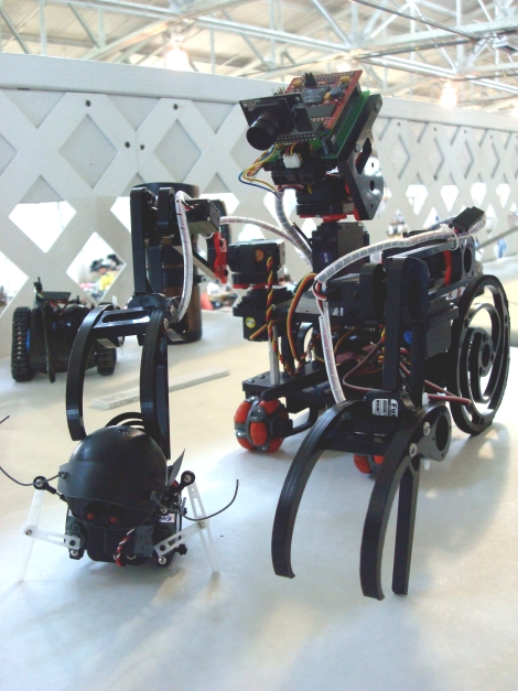
But he had some 'issues' with Fish . . .
More video and pics of ERP at RoboGames coming soon.
July, 2009: Open Source Robot
I've been working on this robot for ~2 years now, so its fairly well developed. So why not share? As such, I'm completely open sourcing this robot. There is one caveat . . . I'm constantly upgrading this robot, so stuff is always changing. I can't promise things will be consistent, and I won't update this with every change I make. Probably only update once a year . . .Mechanics:
1:1 ratio printable dimensions
AutoDesk Inventor Files (compatible with v7+) 8.6mbServos:
HS-311 x 4 (shoulders, camera)
HS-645MG x 2 (shoulders)
HS-225BB x 2 (wheels)
S3114 x 2 (grippers)
S3102 x 2 (elbows)Software:
Axon code
ERP code freeze
SoR Biped EngineElectronics:
Axon
BlueSmirf Bluetooth
BlackfinAnd here is a quickie video on assembly:
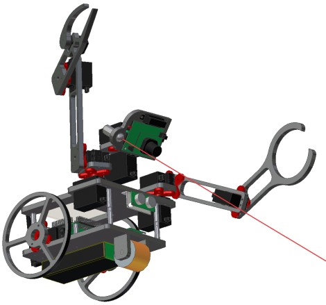
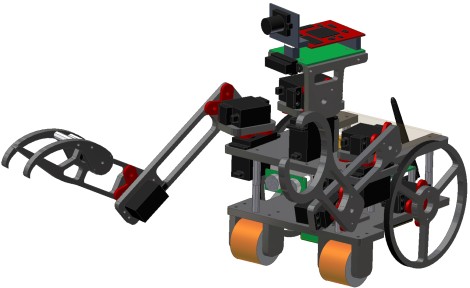
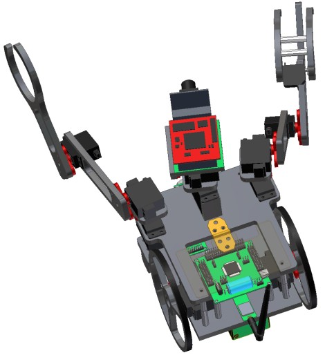
July, 2009: PhotoRealistic CAD
For fun, I did some photorealistic CAD images using Inventor . . .I call this work, 'Wall-ERP'.
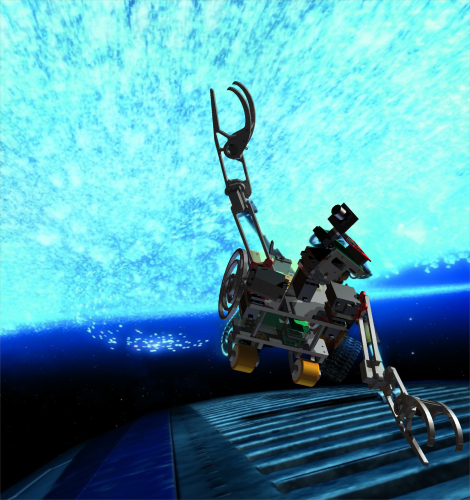
Here is a CAD image with fairly realistic shading.
And this has somewhat of a cartoon-ish feel to it that I like for some reason . . .
February, 2010: Converted to WebbotLib
As WebbotLib is becoming the future in robot programming, with a community of now 200+ people, it would only be proper to move ERP over to it. Actually, the conversion was pretty easy - took me only a day or so to rewrite all my code. Not a single regret, either. =)You can now download it open sourced here: ERP for WebbotLib v1.14
Read the comments in the code to figure out how it works, silly. Not everything new in the code has been tested yet, but anything that worked in the previous version does in the latest version. Its always a work in progress.
And don't forget to link back and credit me for any code snippets you 'borrow'.
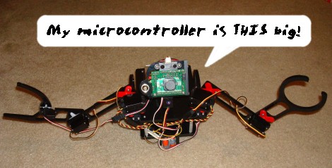
Oh, and I upgraded him with my new Axon II robot microcontroller.
February, 2011: Voice Control
Since my last update I've played around a bit for better object recognition, but mostly just been pre-occupied with other projects.I now have ERP capable of following voice commands in two languages. The second language, Thai, will come in another video later . . .
You can download the code here: ERP for WebbotLib v2.08

Updates:
June, 2007: v1a - Concept
February, 2008: v1b - Upgrade
March, 2008: v1c - Changes
April, 2008: v1c - Vision and Suspension
September, 2008: Robot Arm & Gripper
April, 2009: Biped Engine
June, 2009: Bluetooth & 3D Scanning
June, 2009: ERP at RoboGames 2009
July, 2009: Open Source Robot
July, 2009: PhotoRealistic CAD
February, 2010: WebbotLib conversion
February, 2011: Voice Control
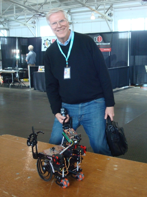
The Experimental Robot Platform
The goal of this robot is to give me a platform that is upgradeable and customizable
so that I would not need to build a new robot chassis for each new idea I want to
try out. This robot will never be 'finished', as I'm always modifying and improving it.
I'll post here after each new major change I make.
As such, I will be slowly documenting these major changes over time. You can keep up with the details and see more pics of the project by subscribing to this forum post.
June, 2007: Concept of ERP Created, v1a
I first got my idea for the ERP in May to create a new 'ultimate' robot. I tend to do this
every two years or so, my previous one being Taurus 2.
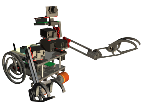
This below CAD video demonstrates what I originally wanted: a pan/tilt camera, wireless data transfer, and a basic differential drive.
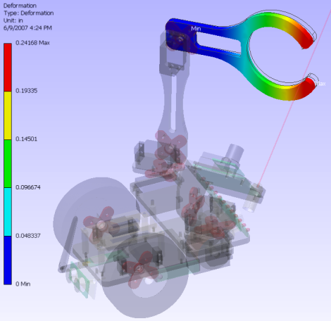
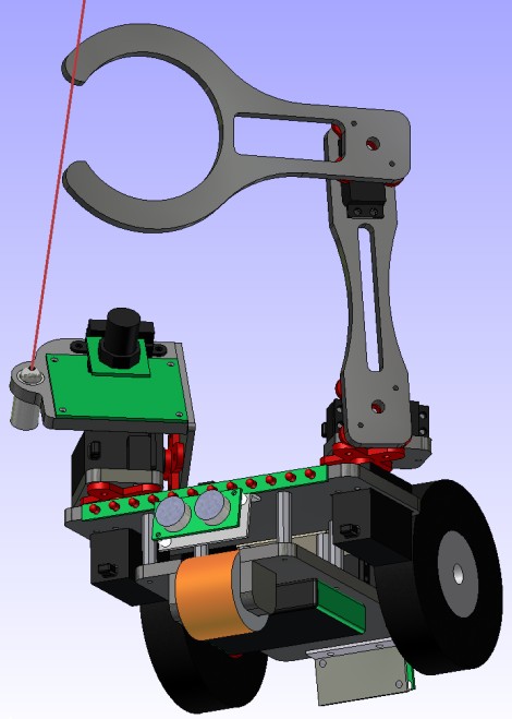
But I quickly decided that this was boring, and the robot needed the ability to interact more with it's surroundings. This is where I decided to add a robot arm, optimizing it using finite element analysis to keep the weight low but the strength high:
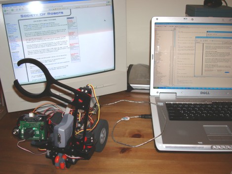
For electronics I decided to use my custom $50 Robot controller, the CMUcam, a Sharp IR, and a pen laser (for pointing, duh).
This is an early test of the ERP's low-level functions:
As its legacy, this robot is what inspired me and was used to write my UART tutorial, bootloader tutorial, and cycle timing tutorial. I also used it to get bluetooth working to transfer data.
I never went much further than that for this version, but here is my source code (as is) for anyone
else interested in taking it further:
ERP source code for $50 Robot controller
February, 2008: ERP Gets Upgraded, v1b
Tons of time had passed between the previous version and this one. The main reason is that I
wanted to control more hardware, and so I needed a controller with tons of new capabilities.
Hence I spent tons of my time working on my Axon microcontroller. I also added a much better
battery, and tons more space for future upgrades of electronics/sensors/etc.
And of course, I wanted hands on two arms that can grab stuff. At this time I was just making a hand on one of the arms - when I'm satisfied with the design, I'll put it on both.
I've been asked on several occasions if I built this using a kit . . . NO!!! Everything was custom made from 'scratch', with the exception of the CMUcam. I designed the whole thing in CAD, and used a CNC to produce the parts.
This video shows the only interesting test I ran:
The first problem was that my custom wheels were too smooth, resulting in too little traction.
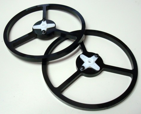
In v1b, I needed really thin yet
wide diameter wheels. I couldn't find any to buy, so I ended up making my own using a CNC. This
is what they look like:
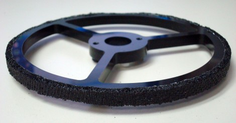
Then pealing off the sticky backing, I slowly rolled the slice around the diameter of the wheel. I used
scissors to clean it up. It works really nicely now:
In other news, I made a strategic partnership with Surveyor Corp. We are trying to integrate the
Blackfin Robot Camera
with my Axon microcontroller, and since I never really liked the CMUcam anyway,
now is the perfect opportunity!
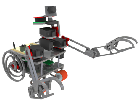
Here are some new CAD images with a few of the changes I made - integrating the new cam, improving
the gripper, and adding a second caster wheel to improve balance.
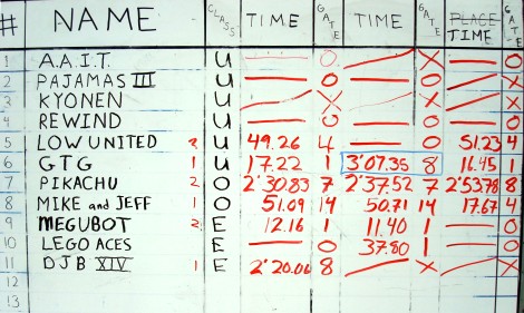
ERP (team Pikachu) won judges choice:
The score:
To learn more about the MOBOT competition and see more videos of it, visit the MOBOT tutorial.
See pics of me and Pikachu (ERP) at c|net's news.com MOBOT 2008 coverage
- I'm on page 6 and 11, wearing all white.
You can also read about it on CMU's official news paper, The Tartan.
I also had to add a suspension system. The earlier versions used two main wheels and a caster for the 3rd balance point.
The problem I was having however is with two swinging arms there was serious balance issues.
To solve this problem, I added a second caster wheel but then I introduced another problem - four points
are not guarenteed to always be on a plane. If the terrain is very unlevel, such as if there were cracks in the ground
or small objects to climb over, one of the balance points will not be in contact causing tipping issues.
To solve this, I invented a single part suspension system which mainly involves design materials to flex exactly
when/where needed. I documented the new concept in my
Single Part Suspension System tutorial, but you
can get the basics from this video I made:
Now for the arms . . . I'm quickly learning that hobbyist servos just do not work well under sudden shock
situations - both electrically and mechanically. The arms have broken a half dozen servos on me already.
The two biggest lessons that I hope you can learn from me are:
March, 2008: ERP Changes, v1c
Since v1b, I've looked into all the problems it had and fixed them all.
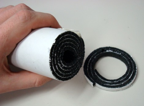
 So to fix that smoothness problem, I just so happened to have a large
sheet of rubber stuff from mcmaster.com with a sticky backing on the other end. Rolling it up, I cut slices into it
using a bandsaw. I tried scissors but it didn't work very well . . .
So to fix that smoothness problem, I just so happened to have a large
sheet of rubber stuff from mcmaster.com with a sticky backing on the other end. Rolling it up, I cut slices into it
using a bandsaw. I tried scissors but it didn't work very well . . .
March, 2008: Vision and Suspension, v1c
More will be reported soon, but for now, enjoy this video of ERP doing vision at MOBOT 2008:
"Initially we awarded the judges' choice to Megubot to reward a good
effort and to encourage participation of young "engineers" like Megan
McKelvey. After seeing the presention on Pikachu and fully appreciating
the level of effort and extrodinary engineering that went into it, we
felt it imperative to reward that effort with a second Judges' Choice award."
- Ben (for the Mobot Committee)
Society of Robots copyright 2005-2014