
 Search Here
MISC
Parts List
Robot Forum
Chat
Member Pages
Axon MCU
Robot Books
Shop
Contact
SKILLS
How To Build
A Robot
Tutorial
Calculators
Mechanics
Programming
Miscellaneous
Robots
Space
HARDWARE
Actuators
Batteries
Electronics
Materials
Microcontrollers
Sensors
SCIENCE
Robot Journals
Robot Theory
Conferences
- weight of each linkage
- weight of each joint
- weight of object to lift
- length of each linkage
- Try to place all three of its pegs in the opponents' goal
- Block opponent pegs from going in your own goal
|
Degrees of Freedom |
About this Robot Arm Tutorial
The robot arm is probably the most mathematically complex robot you could ever build.
As such, this tutorial can't tell you everything you need to know. Instead, I will
cut to the chase and talk about the bare minimum you need to know to build an
effective robot arm. Enjoy!
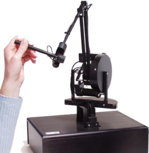
To get you started, here is a video of a robot arm assignment I had when I took Robotic Manipulation back in college. My group programmed it to type the current time into the keyboard . . . (lesson learned, don't crash robot arms into your keyboard at full speed while testing in front of your professor)
You might be also interested in a robot arm I built that can shuffle, cut, and deal playing cards.
Degrees of Freedom (DOF)
The degrees of freedom, or DOF, is a very important term to understand. Each degree of freedom
is a joint on the arm, a place where it can bend or rotate or translate.
You can typically identify the number of degrees of freedom by the number of actuators
on the robot arm. Now this is very important - when building a robot arm you want
as few degrees of freedom allowed for your application!!!
Why? Because each degree requires a motor, often an
encoder, and exponentially complicated algorithms and cost.
Denavit-Hartenberg (DH) Convention
The Robot Arm Free Body Diagram (FBD)
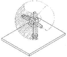
The Denavit-Hartenberg (DH) Convention is the accepted method of drawing robot arms in
FBD's. There are only two motions a joint could make: translate and rotate.
There are only three axes this could happen on: x, y, and z (out of plane).
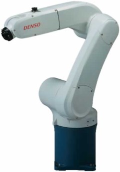
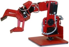
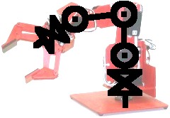
Below I will show a few robot arms, and then draw a FBD next to it,
to demonstrate the DOF relationships and symbols. Note that I did not count the DOF
on the gripper (otherwise known as the end effector). The gripper is often complex
with multiple DOF, so for simplicity it is treated as separate in basic robot arm design.
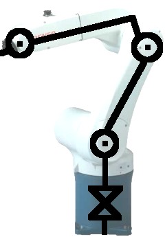
Notice between each DOF there is a linkage of some particular length. Sometimes a joint can have multiple DOF in the same location. An example would be the human shoulder. The shoulder actually has three coincident DOF. If you were to mathematically represent this, you would just say link length = 0.

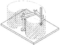
Also note that a DOF has its limitations, known as the configuration space. Not all joints can swivel 360 degrees! A joint has some max angle restriction. For example, no human joint can rotate more than about 200 degrees. Limitations could be from wire wrapping, actuator capabilities, servo max angle, etc. It is a good idea to label each link length and joint max angle on the FBD.
(image credit: Roble.info)
Your robot arm can also be on a mobile base, adding additional DOF. If the wheeled robot can rotate, that is a rotation joint, if it can move forward, then that is a translational joint. This mobile manipulator robot is an example of a 1 DOF arm on a 2 DOF robot (3 DOF total).
Since there are many possible configurations for your robot arm, from now on we
will only talk about the one shown below. I chose this 3 DOF configuration because it is simple,
yet isnt limiting in ability.
Now lets assume that all joints rotate a maximum of 180 degrees, because most
servo motors
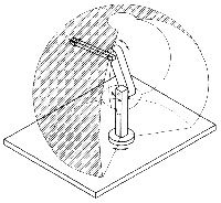
cannot exceed that amount. To determine the workspace, trace all locations that the end effector
can reach as in the image below.
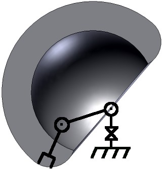
Now rotating that by the base joint another 180 degrees to get 3D, we have this workspace image.
Remember that because it uses servos, all joints are limited to a max of 180 degrees. This creates a workspace
of a shelled semi-sphere (its a shape because I said so).
If you change the link lengths you can get very different sizes of workspaces,
but this would be the general shape. Any location outside of this space is a location
the arm cant reach. If there are objects in the way of the arm, the workspace
can get even more complicated.
Here are a few more robot workspace examples:
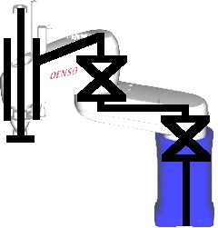
The point of doing force calculations is for motor selection. You must make sure that
the motor you choose can not only support the weight of the robot arm, but also what the
robot arm will carry (the blue ball in the image below).
The first step is to label your FBD, with the robot arm stretched out to its maximum length.
Robot Workspace
The robot workspace (sometimes known as reachable space) is all places that the end effector (gripper) can reach.
The workspace is dependent on the DOF angle/translation limitations, the arm link lengths, the angle at which
something must be picked up at, etc. The workspace is highly dependent on the robot configuration.

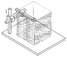
Cartesian Gantry Robot Arm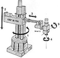
Cylindrical Robot Arm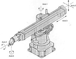
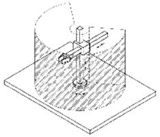
Spherical Robot Arm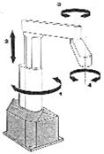
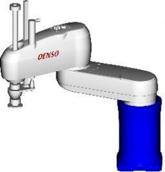
Scara Robot Arm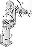
Articulated Robot Arm
Mobile Manipulators
A moving robot with a robot arm is a sub-class of robotic arms.
They work just like other robotic arms, but the DOF of the vehicle is added to the DOF of the arm.
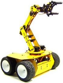
If say you have a differential drive
robot (2 DOF) with a robot arm (5 DOF) attached (see yellow robot below), that
would give the robot arm a total sum of 7 DOF. What do you think the workspace on this
type of robot would be?
Force Calculations of Joints
This is where this tutorial starts getting heavy with math. Before even continuing,
I strongly recommend you read the mechanical engineering tutorials for
statics and dynamics.
This will give you a fundamental understanding of moment arm calculations.
|
Choose these parameters:
|
Next you do a moment arm calculation, multiplying downward force times the linkage lengths. This calculation must be done for each lifting actuator. This particular design has just two DOF that requires lifting, and the center of mass of each linkage is assumed to be Length/2.
Torque About Joint 1:
- M1 = L1/2 * W1 + L1 * W4 + (L1 + L2/2) * W2 + (L1 + L3) * W3
Torque About Joint 2:
- M2 = L2/2 * W2 + L3 * W3
As you can see, for each DOF you add the math gets more complicated, and the joint weights get heavier. You will also see that shorter arm lengths allow for smaller torque requirements.

|
Too lazy to calculate forces and torques yourself? Try my robot arm calculator to do the math for you. |
For our robot arm example, here we calculate end effector location with given
joint angles and link lengths. To make visualization easier for you, I drew blue
triangles and labeled the angles.
Assume that the base is located at x=0 and y=0. The first step would be to
locate x and y of each joint.
Joint 0 (with x and y at base equaling 0):
Joint 1 (with x and y at J1 equaling 0):
Joint 2 (with x and y at J2 equaling 0):
End Effector Location (make sure your signs are correct):
The angle of the end effector, in this example, is equal to theta + psi.
Too lazy to calculate forward kinematics yourself?
Instead, I will just give you the equations for our specific robot design:
So what makes inverse kinematics so hard? Well, other than the fact that it involves
non-linear simultaneous equations, there are other reasons too.
First, there is the very likely possibility of multiple, sometimes infinite, number of solutions (as shown below).
How would your arm choose which is optimal, based on torques, previous arm position, gripping angle, etc.?
There is the possibility of zero solutions. Maybe the location is outside the workspace, or
maybe the point within the workspace must be gripped at an impossible angle.
Singularities, a place of infinite acceleration, can blow up equations and/or leave motors lagging behind
(motors cant achieve infinite acceleration).
And lastly, exponential equations take forever to calculate on a microcontroller.
No point in having advanced equations on a processor that cant keep up.
Too lazy to calculate inverse kinematics yourself?
Suppose your robot arm has objects within its workspace, how does the arm move through
the workspace to reach a certain point? To do this, assume your robot arm is just a simple
mobile robot navigating in 3D space. The end effector will traverse the space just like a
mobile robot, except now it must also make sure the other joints and links do not collide
with anything too. This is extremely difficult to do . . .
What if you want your robot end effector to draw straight lines with a pencil?
Getting it to go from point A to point B in a straight line is relatively simple to solve.
What your robot should do, by using inverse kinematics, is go to many points between point
A and point B. The final motion will come out as a smooth straight line. You can not only
do this method with straight lines, but curved ones too. On expensive professional robotic arms
all you need to do is program two points, and tell the robot how to go between the two points
(straight line, fast as possible, etc.). For further reading, you could use the
wavefront algorithm to plan this two point trajectory.
However the end effector does not just rotate about the base, but can go in many directions. The end effector
can follow a straight line, or curve, etc.
With robot arms, the quickest way between two points is often not a straight line. If two joints have two
different motors, or carry different loads, then max velocity can vary between them. When you tell the
end effector to go from one point to the next, you have two decisions. Have it follow a straight line between
both points, or tell all the joints to go as fast as possible - leaving the end effector to possibly swing
wildly between those points.
In the image below the end effector of the robot arm is moving from the blue point to the red point. In the
top example, the end effector travels a straight line. This is the only possible motion this arm can perform
to travel a straight line. In the bottom example, the arm is told to get to the red point as fast as possible.
Given many different trajectories, the arm goes the method that allows the joints to rotate the fastest.
Which method is better? There are many deciding factors. Usually you want straight lines when the object
the arm moves is really heavy, as it requires the momentum change for movement
(momentum = mass * velocity).
But for maximum speed (perhaps the arm isn't carrying anything, or just light objects) you would want maximum joint speeds.
Now suppose you want your robot arm to operate at a certain rotational velocity, how much torque would a joint need?
First, lets go back to our FBD:
Now lets suppose you want joint J0 to rotate 180 degrees in under 2 seconds, what torque does the J0 motor need?
Well, J0 is not affected by gravity, so all we need to consider is momentum and inertia. Putting this
in equation form we get this:
torque = moment_of_inertia * angular_acceleration
breaking that equation into sub components we get:
torque = (mass * distance^2) * (change_in_angular_velocity / change_in_time)
and
change_in_angular_velocity = (angular_velocity1)-(angular_velocity0)
angular_velocity = change_in_angle / change_in_time
Now assuming at start time 0 that angular_velocity0 is zero, we get
torque = (mass * distance^2) * (angular_velocity / change_in_time)
where distance is defined as the distance from the rotation axis to the center of mass of the arm:
center of mass of the arm = distance = 1/2 * (arm_length)
but you also need to account for the object your arm holds:
center of mass of the object = distance = arm_length
So then calculate torque for both the arm and then again for the object, then add the two torques together for the total:
torque(of_object) + torque(of_arm) = torque(for_motor)
And of course, if J0 was additionally affected by gravity, add the torque required to lift the arm
to the torque required to reach the velocity you need. To avoid doing this by hand, just use the robot arm calculator.
But it gets harder . . . the above equation is for rotational motion and not for straight line motions.
Look up something called a Jacobian if you enjoy mathematical pain =P
Another Video!
Each team programs an arm to do two tasks:
Enjoy! (notice the different arm trajectories)
Arm Sagging
The sagging problem is even worse when the arm wobbles between stop-start motions.
The solve this, implement a PID controller so as to slow
the arm down before it makes a full stop.
A robot arm without video sensing is like an artist painting with his eyes closed. Using basic
visual feedback algorithms, a robot arm could go from point to point on its own without a list of
preprogrammed positions. Giving the arm a red ball, it could actually reach for it (visual tracking and servoing). If the arm can
locate a position in X-Y space of an image, it could then direct the end effector to go to that same X-Y location
(by using inverse kinematics). If you are interested in learning more about the vision aspect of visual servoing, please
read the Computer Vision Tutorials for more information.
Haptic sensing is a little different in that there is a human in the loop. The human controls the robot arm movements
remotely. This could be done by wearing a special glove, or by operating a miniature model with position sensors.
Robotic arms for amputees are doing a form of haptic sensing. Also to note, some robot arms have feed back sensors (such as touch)
that gets directed back to the human (vibrating the glove, locking model joints, etc.).
Tactile sensing (sensing by touch) usually involves force feedback sensors and
current sensors.
These sensors detect collisions by detecting unexpected force/current spikes, meaning a collision has occurred. A robot
end effector can detect a successful grasp, and not grasp too tight or too lightly, just by measuring force.
Another method would be to use current limiters - sudden large current draws generally mean a collision/contact
has occurred. An arm
could also adjust end effector velocity by knowing if it is carrying a heavy object or a light object - perhaps even
identify the object by its weight.
Try this. Close your eyes, and put both of your hands in your lap. Now keeping your eyes closed, move your hand
slowly to reach for your computer mouse. Do it!!!! You will see why soon . . . Now what will happen is
that your hand will partially miss, but at least one of your fingers will touch the mouse. After that finger touches, your
hand will suddenly re-adjust its position because it now knows exactly where that mouse is. This is the benefit
of tactile sensing - no precision encoders required for perfect contact!
In the meantime, you might be interested in reading the tutorial for
calculating friction and force for robot end effectors.
I also went in to some detail describing my robot arm card dealing gripper.
Anyway, I hope you have enjoyed this robot arm tutorial!
Forward Kinematics
Forward kinematics is the method for determining the orientation and position
of the end effector, given the joint angles and link lengths of the robot arm.
To calculate forward kinematics, all you need is highschool trig and algebra.
x0 = 0
y0 = L0
cos(psi) = x1/L1 => x1 = L1*cos(psi)
sin(psi) = y1/L1 => y1 = L1*sin(psi)
sin(theta) = x2/L2 => x2 = L2*sin(theta)
cos(theta) = y2/L2 => y2 = L2*cos(theta)
x0 + x1 + x2, or 0 + L1*cos(psi) + L2*sin(theta)
y0 + y1 + y2, or L0 + L1*sin(psi) + L2*cos(theta)
z equals alpha, in cylindrical coordinates
Check out my Robot Arm Designer v1 in excel.
Inverse Kinematics
Inverse kinematics is the opposite of forward kinematics. This is when you have
a desired end effector position, but need to know the joint angles required to achieve it.
The robot sees a kitten and wants to grab it, what angles should each joint go to?
Although way more useful than forward kinematics, this calculation is much more complicated too. As such,
I will not show you how to derive the equation based on your robot arm configuration.
psi = arccos((x^2 + y^2 - L1^2 - L2^2) / (2 * L1 * L2))
theta = arcsin((y * (L1 + L2 * c2) - x * L2 * s2) / (x^2 + y^2))
where c2 = (x^2 + y^2 - L1^2 - L2^2) / (2 * L1 * L2);
and s2 = sqrt(1 - c2^2);
Check out my Robot Arm Designer v1 in excel.
Motion Planning
Motion planning on a robot arm is fairly complex so I will just give you the basics.
Velocity (and more Motion Planning)
Calculating end effector velocity is mathematically complex, so I will go only into the basics.
The simplest way to do it is assume your robot arm (held straight out) is a rotating wheel of L diameter.
The joint rotates at Y rpm, so therefore the velocity is
Velocity of end effector on straight arm = 2 * pi * radius * rpm
(use arm mass)
(use object mass)
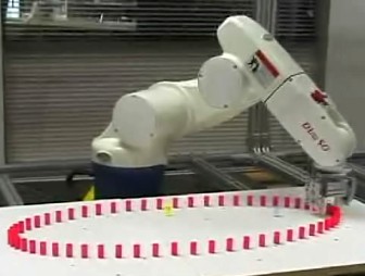
In order to better understand robot arm dynamics, we had a robot arm bowling competition using the same DENSO 6DOF robot arms
as in the clocks video.
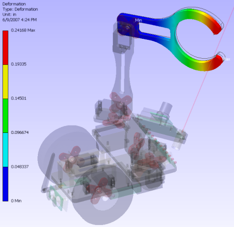
Arm sagging is a common affliction of badly designed robot arms. This is when an arm is too long and heavy,
bending when outwardly stretched. When designing your arm, make sure the arm is reinforced and lightweight.
Do a finite element analysis to determine bending deflection/stress
such as I did on my ERP robot:
 Keep the heaviest components, such as motors, as close to the robot arm base as possible.
It might be a good idea for the middle arm joint to be chain/belt driven by a motor located at the base
(to keep the heavy motor on the base and off the arm).
Keep the heaviest components, such as motors, as close to the robot arm base as possible.
It might be a good idea for the middle arm joint to be chain/belt driven by a motor located at the base
(to keep the heavy motor on the base and off the arm).
Sensing
Most robot arms only have internal sensors, such as encoders.
But for good reasons you may want to add additional sensors, such
as video, touch, haptic, etc.
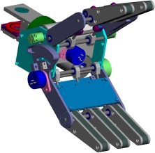
End Effector Design
In the future I will write a separate tutorial on how to design robot grippers, as it will require many more
pages of material.
Society of Robots copyright 2005-2014