
 Search Here
MISC
Parts List
Robot Forum
Chat
Member Pages
Axon MCU
Robot Books
Shop
Contact
SKILLS
How To Build
A Robot
Tutorial
Calculators
Mechanics
Programming
Miscellaneous
Robots
Space
HARDWARE
Actuators
Batteries
Electronics
Materials
Microcontrollers
Sensors
SCIENCE
Robot Journals
Robot Theory
Conferences
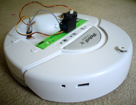
The iRobot Create
The iRobot Create is
a commercial robot hacked up from a previous robot vacuum cleaner they produced.
They have been trying to encourage the hobbyist and educational community to start
developing these things and through one of their schemes I landed a free Create
to toy with.
A video of the robot running around my house using the default programming:
My end goal of this project was to implement real-time SLAM (simultaneous localization and mapping) onto the robot. But I made this plan before I was aware of the capabilities (i.e. limitations) of the iRobot. For a start, it only uses the ATmega168 microcontroller. This is incredibly slow with huge memory limitations!
Instead I decided to implement real-time adaptive mapping, and just have it update the map with new scans. Its not matching to an old map such as in SLAM, but it is still updating to remove the accumulated navigation errors.
The Create Command Structure
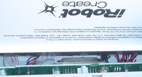
To communicate with the Create, you must send serial commands to its magical green box circuit board
thingy inside the Create. Upon breaking this made-in-China box open I still couldn't make out most of the electronics . . .
So to send these serial commands, we must program the Command Module. This green box thing has an ATmega168 microcontroller inside, a common and easier microcontroller to use. This is the same microcontroller Im using on the $50 Robot, so all the source code is cross-platform.
Now so to command the Create to do stuff, all you do is occasionally send commands to it from your ATmega168. You can also ask for sensor data from it using the delayAndUpdateSensors(update_delay); command in my source code.
The Create Encoders
The Create does have high resolution encoders,
but I'm not sure what the resolution is because its
not in any of the manuals.
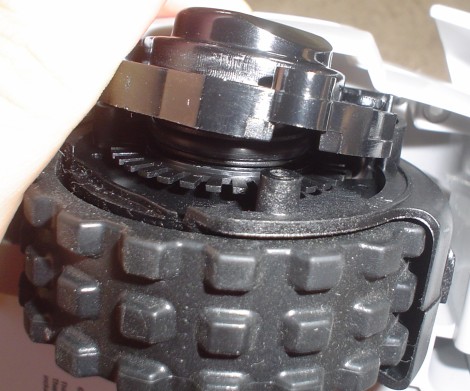
Yet despite the high-resolution encoders, they are still inaccurate. I'm not sure if its dust or what, but the counts were constantly skipping. I wouldn't rely on the encoder at all.
The sample software that comes with the iRobot Create does not effectively use the encoders. It only does a point and shoot kind of algorithm for angle rotations, and does a 'good enough' algorithm for distance measurement. The source code doesn't even use the 156 (wait for distance) or 157 (wait for angle) commands! Of course, for their uses, the source didn't need these commands. But I need perfect encoder measurements for encoder based navigation.
So I had to write up my own stuff . . . First I tried implementing the 156 and 157 commands but for some reason it occasionally didn't work. Strange things happened, even resulting in program crashes. And even when it did work, the encoder measurements were still error-ing (its a word because I made it up).
The best I could is with my own written methods. Use these functions for somewhat
accurate Create movement:
//rotate clockwise (CW) and counter-clockwise (CCW)
rotate_CCW(180,250); //(angle, rotation_speed)
rotate_CW(90,150); //(angle, rotation_speed)

//move straight (use negative velocity to go in reverse)
straight(cell_size,100); //(distance, velocity)

stop();//don't make me explain this function!!!
Although it doesn't correct for overshoot or undershoot, it at least keeps track of it to account for it in the next motion. This still results in error, but not as much as before.
The Stampy Edge Detection Algorithm
To start off my robots' adventures, I needed to implement a basic highly reactive algorithm
to test out my proto-code and sensor setup.
I decided to implement my Stampy Edge Detection algorithm.
I originally developed this algorithm for my Stampy sumo robot so that it can quickly locate the enemy robot. But I also found many other neat tricks that the algorithm can do, such as with my outdoor line following robot that uses a single photoresistor!
The concept is simple. A scanning Sharp IR rangefinder does only two things:
If no object is seen, the scanner turns right.
If an object is seen, the scanner turns left.
As shown, the scanner goes left if it sees a googly-eyed robot. If it doesn't detect it, the scanner turns right until it does. As a result, the scanner converges on the left edge of the googly-eyed robot:
Now the robot always keeps track of the angle of the scanner. So if the scanner is pointing left, the robot turns left. If the scanner is pointing right, the robot turns right. And of course, if the scanner is pointing straight ahead, the robot just drives straight ahead.
For more detailed info, visit my write-up on my Stampy sumo robot.
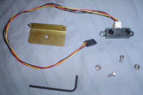
Building the Scanner
The first step to the hardware is to make a mount for the scanner. Below are the parts you
need, followed by a video showing how everything is assembled.
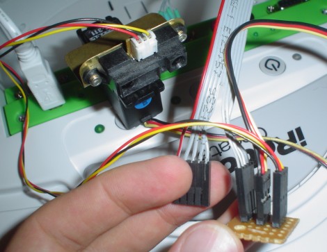
Wiring up the Hardware
Now I needed to get some wiring to attach the servo and Sharp IR to the Create robot serial port.
Going through my box of scrap wire, I found this.
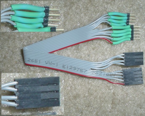
To make it, I just took some serial cable and put some headers on it with heatshrink. You can use whatever you want.
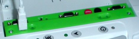
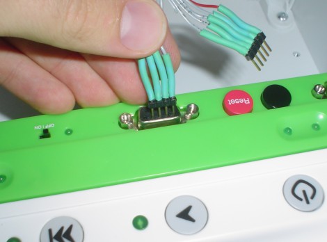
Then I plugged it into the center serial port as so:
How do I know which pins in the serial port do I use? Well, I looked up the pin-out in the manual:
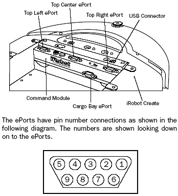
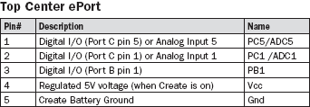
To distribute wiring (with a power bus), you need four pins: power and ground, an analog pin for the sensor, and a digital output pin for the servo. What does that mean? Connect all the grounds (black) to each other, and connect all the power lines (red) to each other. Each signal line (yellow) gets its own serial cable wire.
To make a power bus, I got a piece of breadboard and male headers as such:
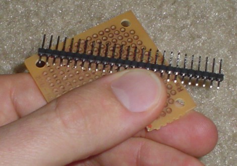
Then I used a Dremel to cut off a small piece of it, and soldered on the headers with the proper power distributing wiring:
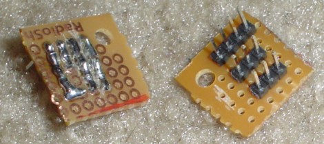
Then I plugged in everything to the power bus as so. Refer to the pin-out in the previous step to make sure where everything plugs in to.
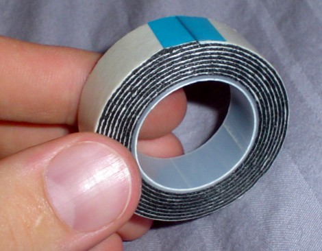
The last step is to attach the servo. You need to have the Sharp IR sensor centrally located, and the only place I can find available was that large empty space in the center (it was a no-brainer). I didn't want to drill holes or make a special mount (too much unnecessary effort), so I decided to use extra strength double sided sticky tape (see below image). My only concern about this tape was that I may have difficulties removing the servo in the future . . . (its not a ghetto mount, this stuff really holds).
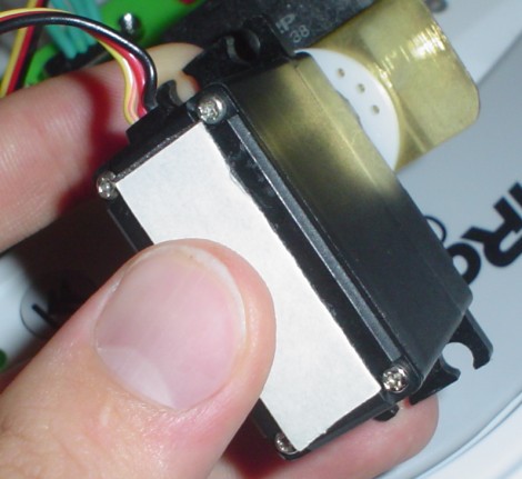
To attach the servo on, I cut a piece off and stuck it to the bottom of my servo:
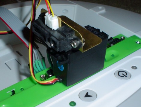
And then I stuck the other side of the tape onto the robot as so:
Programming the iRobot Create with Mod
There are many ways to program your Create. iRobot recommends you using
WinAVR (22.8mb)
as do I. Install that program. But I prefer to program using the IDE called
AVR Studio, version 4.13, build 528 (73.8mb).
An optional install.
I wont go into detail in programming the Create because the manual tells you how. But if you are still curious how I did it, here is my write-up on how to program an AVR.
Unfortunately I was never able to get AVR Studio to communicate with my Create . . . so instead I used AVR Dude (that came with WinAVR). To do this, I just opened up a command window and did stuff like this (click to enlarge):

avrdude -p atmega168 -P com9 -c stk500 -U flash:w:iRobot.hex
Again, its all in the Create manuals.
To help you get started, here is my source code:
iRobot Create Sharp IR Scanner source code (August 20th, 2007)
After uploading the program, just turn on your robot, push the black button, and off to attacking cute kittens it goes!
Enjoy the video:
Yes, it is programmed to chase a can of beer . . .
Robot Navigation
The next step to programming more intelligence into your robot is for it to have memory,
and then to make plans with that memory.
In this case, it will store maps of places the robot can 'see'. Then by using these maps, the robot can then navigate around obstacles intelligently to reach goals. The robot can also update these maps so that it accounts for people moving around in the area.
The method I used for this is the wavefront algorithm, using a Sharp IR scanner as my sensor. The scanner would do a high-resolution scan so that it can find even the smallest of objects. If anything is detected in a block, even something as thin as a chair leg (the enemy of robots), it will consider the entire block impassable. Why would I do this? Because the memory on a microcontroller is limited and cannot store massive amounts of data. In fact, it was incapable of storing maps greater than 20x20!!! Plus, the increase in robot movement efficiency does not compare to the much larger increase in computational inefficiency.
A quick example of what the map would look like:
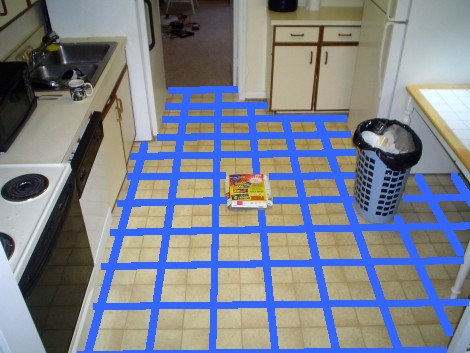
I decided that the 'world' should be discretized into square units exactly the same size as the robot. This way each movement the robot takes will be one robot unit length. Why did I do this? Computational simplicity. Higher map resolution requires more processing power. But for a home scenario high accuracy isn't required, so no need to get complicated. As you can see, each terrain situation requires a different optimal discretization . . . Remember to check out my wavefront algorithm tutorial if you want to learn more.
Results
Enjoy! Notice that its an unedited video:
And what you have really been waiting for, the WaveFront Source Code:
iRobot Create WaveFront Source Code (September 9th 2007)
Also, videos showing whats inside a Roomba vacuum, just to see what you can hack out of it.
Society of Robots copyright 2005-2014