
 Search Here
MISC
Parts List
Robot Forum
Chat
Member Pages
Axon MCU
Robot Books
Shop
Contact
SKILLS
How To Build
A Robot
Tutorial
Calculators
Mechanics
Programming
Miscellaneous
Robots
Space
HARDWARE
Actuators
Batteries
Electronics
Materials
Microcontrollers
Sensors
SCIENCE
Robot Journals
Robot Theory
Conferences
- connect the Rx and Tx of the UART together
- printf the letter 'A'
- have an if statement turn on a LED if 'A' is received
|
What is the UART?
The UART, or Universal Asynchronous Receiver / Transmitter, is a feature of your
microcontroller useful for communicating
serial data (text, numbers, etc.) to your PC. The device changes incoming parallel information (within the microcontroller/PC)
to serial data which can be sent on a communication line.
Adding UART functionality is extremely useful for robotics. With the UART, you can add an LCD, bootloading, bluetooth wireless, make a datalogger, debug code, test sensors, and much more!
Understanding the UART could be complicated, so I filtered out the useless information and present to you only the useful need-to-know details in an easy to understand way . . . The first half of this tutorial will explain what the UART is, while the second half will give you instructions on how to add UART functionality to your $50 robot.
What is RS232, EIA-232, TTL, serial, and USB?
These are the different standards/protocols used from transmitting data. They are incompatible with each other,
but if you understand what each is, then you can easily convert them to what you need for your robot.
Back in the day circuits were noisy, lacking filters and robust algorithms, etc. Wiring was also poor, meaning signals
became weaker as wiring became longer (relates to resistance of the wire). So to compensate for the signal loss,
they used very high voltages. Since a serial signal is basically a square wave, where the wavelengths relate to the
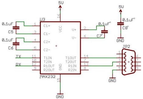
bit data transmitted, RS232 was standardized as +/-12V. To get both +12V and -12V, the most common method is to
use the MAX232 IC (or ICL232 or ST232 - different IC's that all do the same thing),
accompanied with a few capacitors and a DB9 connector. But personally, I feel
wiring these up is just a pain . . . here is a schematic if you want to do it yourself (instead of a kit):
Instead what you can use is something called the RS232 shifter - a circuit that takes signals from the
computer/microcontroller (TTL) and correctly inverts and amplifies the serial signals to
the EIA232F standard.
If you'd like to learn more about these standards, check out this
RS232 and EIA232 tutorial (external site).
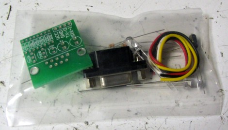
The cheapest RS232 shifter I've found is the $7
RS232 Shifter Board Kit
from SparkFun. They have schematics of their board posted if you'd rather make your own.
This is the RS232 shifter kit in the baggy it came in . . .
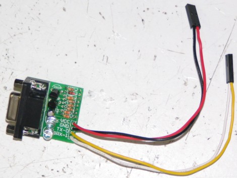
And this is the assembled image. Notice that I added some useful
wire connectors
that did not come with the kit so that I may easily connect it to
the headers on my microcontroller board. Also notice how two wires
are connected to power/ground, and the other two are for Tx and Rx
(I'll explain this later in the tutorial).
You really do not need to understand what TTL is, other than that TLL is the signal
transmitted and received by your microcontroller UART. This TTL signal is different from what your
PC serial/USB port understands, so you would need to convert the signal.
You also do not really need to understand USB, other than that its fast becoming
the only method to communicate with your PC using external hardware.
To use USB with your robot, you will
need an adaptor that converts to USB. You can easily find converters under $20,
or you can make your own by using either the FT232RL or CP2102 IC's.
For example:
If you wanted bluetooth wireless,
get a TTL to bluetooth adaptor, or if you want ethernet, get a TTL to ethernet adaptor, etc.
There are many combinations, just choose one based on what adaptors/requirements you have.
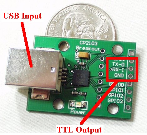
For example, if your laptop only has USB, buy a TTL to USB adaptor as shown with my
SparkFun Breakout Board for CP2103 USB:
There are other cheaper ones you can buy today, you just need to look around.
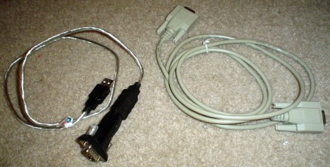
On the left of this below image is my $15 USB to RS232 adaptor, and the right cable
is my RS232 extension cable for those robots that like to run around:
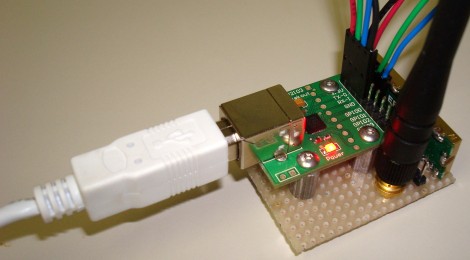
Below is my USB to wireless adaptor that I made in 2007
(although now companies sell them wired up for you). It converts a USB type signal to a TTL
type signal, and then my Easy Radio wireless transmitter converts it again to a method
easily transmitted by air to my robot:
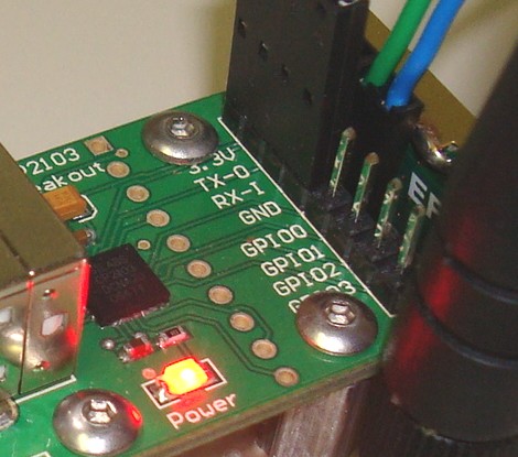
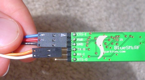
And a close-up of the outputs. I soldered on a male header row and connected
the ground, Tx, and Rx to my wireless transmitter. I will talk about Tx and Rx soon:
Even my bluetooth transceiver has the same Tx/Rx/Power/Ground wiring:
If you have a CMUcam or GPS, again, the same connections.
Other Terminology . . .
For example, suppose you have a GPS device that transmits a TTL signal and you want to connect
this GPS to your microcontroller UART. This is how you would do it:
Notice how Tx is connected to Rx, and Rx is connected to Tx. If you connect Tx to Tx, stuff
will fry and kittens will cry. If you are the type of person to accidentally plug in your
wiring backwards, you may want to add a resistor of say ~2kohm coming out of your UART to each pin.
This way if you connect Tx to Tx accidentally, the resistor will absorb all the bad ju-ju (current that will
otherwise fry your UART).
Tx pin -> connector wire -> resistor -> Rx pin
And remember to make your ground connection common!
For example, your robot would pass sensor data to your laptop at 38400 bits per second and your
laptop would listen for this stream of 1s and 0s expecting a new bit every
1/38400bps = 26us (0.000026 seconds). As long as the robot outputs bits at the pre-determined speed,
your laptop can understand it.
Remember to always configure all your devices to the same baud rate for communication to work!
Data bits, Parity, Stop Bits, Flow Control
Bit Banging
One solution would be to have both devices share the same clock source, but that just adds extra wires . . . All
of this is handled automatically by the UART, but if you would like to understand more, continue reading . . .
Asynchronous transmission allows data to be transmitted without the sender having to send a clock signal to the receiver.
Instead, the sender and receiver must agree on timing parameters in advance and special bits are added to each word which
are used to synchronize the sending and receiving units.
When a word is given to the UART for Asynchronous transmissions, a bit called the "Start Bit" is added to the beginning of
each word that is to be transmitted. The Start Bit is used to alert the receiver that a word of data is about to be sent,
and to force the clock in the receiver into synchronization with the clock in the transmitter. These two clocks must be
accurate enough to not have the frequency drift by more than 10% during the transmission of the remaining bits in the word.
(This requirement was set in the days of mechanical teleprinters and is easily met by modern electronic equipment.)
When data is being transmitted, the sender does not know when the receiver has 'looked' at the value of the bit -
the sender only knows when the clock says to begin transmitting the next bit of the word.
When the entire data word has been sent, the transmitter may add a Parity Bit that the transmitter generates. The Parity
Bit may be used by the receiver to perform simple error checking. Then at least one Stop Bit is sent by the transmitter.
When the receiver has received all of the bits in the data word, it may check for the Parity Bits (both sender and receiver
must agree on whether a Parity Bit is to be used), and then the receiver looks for a Stop Bit. If the Stop Bit does not
appear when it is supposed to, the UART considers the entire word to be garbled and will report a Framing Error to the host
processor when the data word is read. The usual cause of a Framing Error is that the sender and receiver clocks were not
running at the same speed, or that the signal was interrupted.
Regardless of whether the data was received correctly or not, the UART automatically discards the Start, Parity and Stop
bits. If the sender and receiver are configured identically, these bits are not passed to the host.
If another word is ready for transmission, the Start Bit for the new word can be sent as soon as the Stop Bit for the
previous word has been sent.
In short, asynchronous data is 'self synchronizing'.
For example, suppose you are transmitting a signal from your microcontroller UART
through a TTL to USB converter to your laptop and it isn't working. All it takes
is one failure point for the entire system to not work, but how do you find it?
The trick is to connect the Rx to the Tx, hence the loop-back test.
For example, to verify that the UART is outputting correctly:
If it still doesn't work, you know that your code was the failure point (if not more than one failure point).
Then do this again on the PC side using HyperTerminal,
directly connecting Tx and Rx of your USB port.
And then yet again using the TTL to USB adaptor.
You get the idea . . .
I'm willing to bet that if you have a problem getting it to work, it is because your
baud rates aren't the same/synchronized.
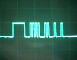
You may also find it useful to connect your Tx line to an oscilloscope to verify
your transmitting frequency:
Top waveform: UART transmitted 0x0F
Full and Half Duplex
Please check out the step-by-step instructions on
how to add UART functionality to your $50 robot >>>.
RS232
RS232 is the old standard and is starting to become obsolete. Few if any laptops even have RS232 ports (serial ports)
today, with USB becoming the new universal standard for attaching hardware. But since the world
has not yet fully swapped over, you may encounter a need to understand this standard.
EIA232F
Today signal transmission systems are much more robust, meaning a +/-12V signal is unnecessary. The EIA232F standard (introduced in 1997)
is basically the same as the RS232 standard, but now it can accept a much more reasonable 0V to 5V signal.
Almost all current computers (after 2002) utilize a serial port based on this EIA-232 standard.
This is great, because now you no longer need the annoying MAX232 circuit!
TTL and USB
The UART takes bytes of data and transmits the individual bits in a sequential fashion. At the
destination, a second UART re-assembles the bits into complete bytes.
Signal Adaptor Examples
Without going into the details, and without you needing to understand them, all
you really need to do is just buy an adaptor.
TTL -> TTL to RS232 adaptor -> PC
TTL -> TTL to EIA-232 adaptor -> PC
TTL -> TTL to EIA-232 adaptor -> EIA-232 to USB adaptor -> PC
TTL -> TTL to USB adaptor -> PC
TTL -> TTL to wireless adaptor -> wireless to USB adaptor -> PC
Tx and Rx
As you probably guessed, Tx represents transmit and Rx represents receive.
The transmit pin always transmits data, and the receive pin always receives it.
Sounds easy, but it can be a bit confusing . . .
Baud Rate
Baud is a measurement of transmission speed in asynchronous communication.
The computer, any adaptors, and the UART must all agree on a single speed of information - 'bits per second'.
The short answer: don't worry about it.
These are basically variations of the signal, each with long explanations of why you would/wouldn't use them.
Stick with the defaults, and make sure you follow the suggested
settings of your adaptor. Usually you will use 8 data bits, no parity, 1 stop bit, and no flow control -
but not always. Note that if you are using a PIC microcontroller you would have to declare these settings in your code (google for sample code, etc).
I will talk a little more about this in coming sections, but mostly just don't worry about it.
What if by rare chance your microcontroller does not have a UART (check the datasheet), or you need
a second UART but your microcontroller only has one? There is still another method, called bit banging.
To sum it up, you send your signal directly to a digital input/output port and manually toggle the port to create
the TTL signal. This method is fairly slow and painful, but it works . . .
Asynchronous Serial Transmission
As you should already know, baud rate defines bits sent per second. But baud only has meaning if the two communicating
devices have a synchronized clock. For example, what if your microcontroller crystal has a slight deviation of .1 second,
meaning it thinks 1 second is actually 1.1 seconds long. This could cause your baud rates to break!
The Loop-Back Test
The loop-back test is a simple way to verify that your UART is working, as well
as to locate the failure point of your UART communication setup.
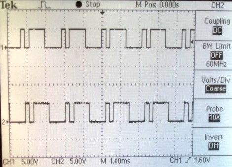
Bottom waveform: UART received 0x0F
Adding UART Functions to AVR and your $50 Robot
To add UART functionality to your $50 robot
(or any AVR based microcontroller) you need to make a few minor modifications to your code
and add a small amount of extra hardware.
Full Duplex is defined by the ability of a UART to simultaneously send and receive data. Half Duplex
is when a device must pause either transmitting or receiving to perform the other. A Half Duplex
UART cannot send and receive data simultaneously. While most microcontroller
UARTs are Full Duplex, most wireless transceivers are Half Duplex. This is due to the fact that
it is difficult to send two different signals at the same time under the same frequency, resulting
in data collision. If your robot is wirelessly transmitting data, in effect it will not be able to
receive commands during that transmission, assuming it is using a Half Duplex transmitter.
Society of Robots copyright 2005-2014