
 Search Here
MISC
Parts List
Robot Forum
Chat
Member Pages
Axon MCU
Robot Books
Shop
Contact
SKILLS
How To Build
A Robot
Tutorial
Calculators
Mechanics
Programming
Miscellaneous
Robots
Space
HARDWARE
Actuators
Batteries
Electronics
Materials
Microcontrollers
Sensors
SCIENCE
Robot Journals
Robot Theory
Conferences
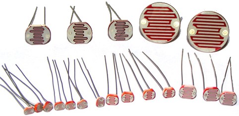
The Photoresistor
Photoresistors (also often called phototransistors or
CdS photoconductive photocells; use 'photocell' for digikey) are simple resistors that altar resistance
depending on the amount of light place over them. More light means less resistance.
Photoresistors are probably the most common, the most affordable ($1-$2 each), and the easiest of all robot sensors to implement. Not only useful for photovore robots and color sensors, but could also act as an optical switch (non-mechanical button) too. For example, wave your hand in front of the robot to block the light in front of it thereby activating something.
To use them as a sensor, measure the voltage drop across the resistor with the analog port of your microcontroller (because a change in resistance means a change in voltage). There are two ways to implement photoresistors:
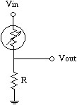
Photoresistor Voltage Divider Circuits
|
Voltage Increases with Light
To choose resistor values, solve this equation:
|
|
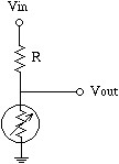
Voltage Decreases with Light
To choose resistor values, solve this equation:
|
Solving the Equations to Determine Resistance, R
There are three steps to determining what resistor you should use for R. To do this,
you first need to get out a multi-meter and measure the resistance across the photoresistor
in two situations. The first situation is the darkest light your robot photoresistor
will see. For example, if you expect your robot to function in a dark room, cover up the photoresistor
entirely and measure the resistance.
The second situation is for the brightest light your robot will see. If you want your robot to operate in your kitchen, measure the photoresistor resistance in the kitchen.
Now all you do is multiply both resistance values, then find the square root of the total. This is the resistor you should use.
OPTIONAL
I would like to thank our SoR Robot Forum member 'ribs' for deriving the above equation. If you want to see the math, have a look. Its not necessary to understand it, so don't panic!
The starting equation I derived using basic circuit math:
voltage difference = absolute_value((R*Vin)/(R+Rp_dark) - (R*Vin)/(R+Rp_bright))
And ribs rewriting the above equation:
F(x)=x/(x+Rd) - x/(x+Rb)
(x = resistance of second resistor, Rd = Rp_dark, Rb = Rp_bright)
Take the derivative (quotient rule, twice)
F'(x) = (x+Rd-x)/(x+Rd)2 - (x+Rb-x)/(x+Rb)2
F'(x) = (x+Rd-x)/(x+Rd)2 - (x+Rb-x)/(x+Rb)2
F'(x) = Rd/(x+Rd)2 - Rb/(x+Rb)2
F'(x) = Rd*(x+Rb)2/{(x+Rd)2*(x+Rb)2} - Rb*(x+Rd)2/{(x+Rd)2*(x+Rb)2}
F'(x) = {Rd*(x+Rb)2 - Rb*(x+Rd)2} / {(x+Rd)2*(x+Rb)2}
F(x) is at a maximum when F'(x) = 0, so set
0 = {Rd*(x+Rb)2 - Rb*(x+Rd)2} / {(x+Rd)2*(x+Rb)2}
Lose the denominator (0/anthing = 0)
0 = Rd*(x+Rb)2 - Rb*(x+Rd)2
0 = Rd*x2+2*Rd*Rb*x+Rd*Rb2 - Rb*x2-2*Rd*Rb*x-Rb*Rd2
0 = Rd*x2+2*Rd*Rb*x+Rd*Rb2 - Rb*x2-2*Rd*Rb*x-Rb*Rd2
0 = Rd*x2-Rb*x2 + Rd*Rb2 - Rb*Rd2
0 = (Rd-Rb)*x2 + (Rb-Rd)*(Rd*Rb)
(Rb-Rd)*x2 = (Rb-Rd)*(Rd*Rb)
(Rb-Rd)*x2 = (Rb-Rd)*(Rd*Rb)
x2 = (Rd*Rb)
x = sqrt(Rd*Rb)
OPTIONAL
Here is another method to determine the resistance so that you may visualize why the equation works. This is also not required, but more of a 'for your information' thing . . .
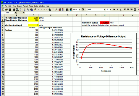
After finding both R_dark and R_bright, you will have to graph the voltage difference given this equation:
voltage difference = absolute_value((R*Vin)/(R+Rp_dark) - (R*Vin)/(R+Rp_bright))
Or you can download this excel sheet to calculate the resistor for you. Enter in the minimum and maximum photoresistor values in the yellow boxes at the top left. A red box will tell you the maximum voltage difference obtainable. Choose the resistor in the list that shows this maximum voltage difference, and use that in the schematic above.
For more info on analyzing sensors with excel, have a look at the advanced sensor interpretation tutorial for data analysis optimization.
Wiring Your Photoresistor for a Microcontroller
Now I will show you how to wire up your photoresistor for use on the microcontroller
I developed for The $50 Robot Tutorial.
It is designed to increase voltage as light increases in order to be more intuitive
to use. I also go over a few of my general wiring techniques you might find useful.
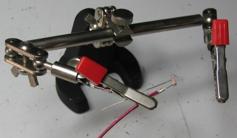
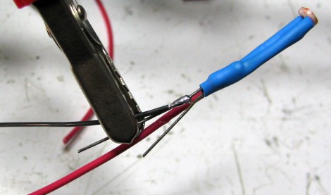
To start off, I want to tell you about a tool I use. Unless you are one of the .00001% of the world population that has a third arm, you should really get one of these alligator clip holder things. They really come in handy!
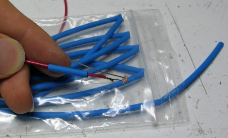
Place a red wire (for power) onto your photoresistor as shown and solder it on. You can also get a friend/parent/sibling/gf to take a chance on your amazing soldering skills to hold the wires together . . . =P
Now using heatshrink cover up the exposed wire. You can heat the heatshrink with a heat gun or hairdryer, but be careful to not heat the sensor as it could damage it. If you don't have heatshrink, you can also use electrical tape.
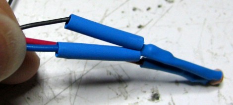
Now that the heatshrink has been um . . . shrunk . . . Attach the resistor as shown and solder it on.
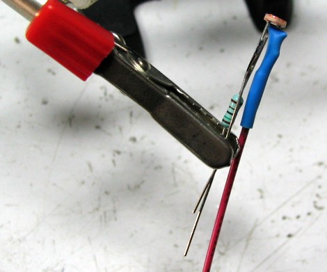
Again, heat shrink it so as the wires are protected. Then solder a black wire (for ground) to the end of the resistor. After covering up the resistor, you do remember which wire belongs to the resistor, right? ;)
You will also want to solder a blue (or whatever color) wire to the other wire coming out. Then heat shrink both of those, too. Remember to not heat it for too long or the sensor might get damaged.
You are now mostly finished, but have a few additional optional steps.
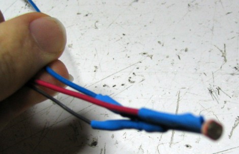
Strip the ends of the three wires for more soldering. Then I like to braid my sensor wires using my amazing girl scout camp skills (don't ask). This is to keep wires from getting tangled and lets you bend/point the photoresistor sensor in the desired direction. Wrap a twist-tie around the end to hold the wires together for the following steps.
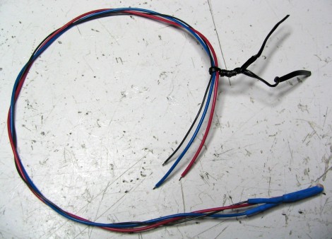
Now you have the option of soldering those three wires directly to your circuit or doing the nicer crimping with a molex method. To solder, you want the black wire attached to ground, the red to a voltage regulator output, and the blue (signal wire) connected to an analog to digital converter pin on your microcontroller. If you are following the The $50 Robot Tutorial, reference the schematic if you arent sure.
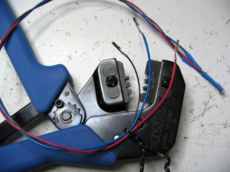
If you decide to do the more complicated crimping method, please continue (otherwise you are done). Using a crimper (~$100), crimp on the connectors as shown.
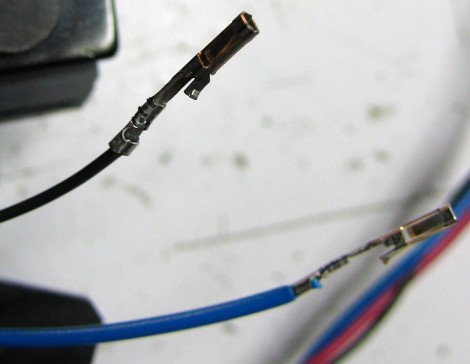
For more detailed information, please check out my full tutorial on how to make wire connectors.
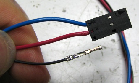
Then stick each of the three wires into the molex connector. Make sure you put them in the right order (the red wire MUST be in the center).
And there you have it, a complete photoresistor sensor ready for a microcontroller!
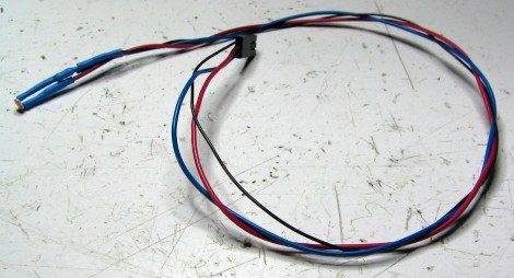
Again, for more detailed instructions, please check out my full tutorial on how to make wire connectors.
Society of Robots copyright 2005-2014