
 Search Here
MISC
Parts List
Robot Forum
Chat
Member Pages
Axon MCU
Robot Books
Shop
Contact
SKILLS
How To Build
A Robot
Tutorial
Calculators
Mechanics
Programming
Miscellaneous
Robots
Space
HARDWARE
Actuators
Batteries
Electronics
Materials
Microcontrollers
Sensors
SCIENCE
Robot Journals
Robot Theory
Conferences
The Sharp IR Range Finder is probably the most powerful sensor available to the everyday robot hobbyist. It is extremely effective, easy to use, very affordable ($10-$20), very small, good range (inches to meters), and has low power consumption.
How it Works
The Sharp IR Range Finder works by the process of triangulation.
A pulse of light (wavelength range of 850nm +/-70nm)
is emitted and then reflected back (or not reflected at all).
When the light returns it comes back at an angle that is dependent on
the distance of the reflecting object. Triangulation works by detecting
this reflected beam angle - by knowing the angle, distance can
then be determined.
The IR range finder reciever has a special precision lens that transmits
the reflected light onto an enclosed linear CCD array based on the triangulation
angle. The CCD array then determines the angle and causes the rangefinder
to then give a corresponding *analog value to
be read by your microcontroller.
Additional to this, the Sharp IR Range Finder circuitry applies a modulated
frequency to the emitted IR beam. This ranging method is almost immune to
interference from ambient light, and offers amazing indifference to the color
of the object being detected. In other words, the sensor is capable of detecting
a black wall in full sunlight with almost zero noise.
(UPDATE: despite popular belief, it is quite possible for both direct and indirect sunlight to significantly affect results. I learned this the hard way!)
Beam Width
A major problem/advantage you may have with the Sharp IR rangefinder is beam width.
Unlike sonar, its fairly thin -
meaning to detect an object your sensor must basically point directly at that object.
Beware of chair legs! hehe . . .
So just how thin is the emitted IR beam? Well getting out my trusty IR detector thingy, its about this big:
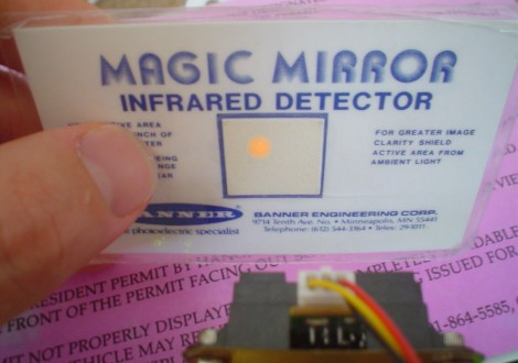
The detector changes IR light into orange-ish light. Ok so that image is partly faked because my digital camera for some reason couldnt see the orange light, so I re-drew it in for you to see. The beam width is the same diameter as the lens on the left of the Sharp IR rangefinder. As the IR detector was moved away, the beam fades and the diameter expands.
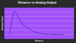
Non-Linear Ouput
The Sharp IR has a non-linear output. This means that as the distance increases linearly
(by set increments), the analog output increases/decreases non-linearly. The image above is a
typical expected output from your range finder. Notice the strange kink in the beginning
of the graph. This is because the range finder is not capable of detecting very short
distances. Refer to the particular range finder you are using to determine the range
that your range finder is capable of.
To effectively use your Sharp IR Range Finder, you must have a voltage output versus distance chart to reference from. The manuals now come with a 'typical response curve' graph for you to use, but you should check just to make sure it is accurate. If you do not have a chart, or you would like to verify the chart, run an experiment that measures distance versus the output analog value. To do this, place an object in front of your sensor, measure the distance, then look at the printf output reading. Graph your data. I recommend reading my article on advanced sensor interpretation to help you make better sense of the data. Typically people either create a lookup table or create a representative equation of the distance function.
To minimize any noise, do this experiment in the environment you wish your robot to operate in. For example, if you want your robot to operate on a factory floor, run this experiment on a factory floor - this will make sure all ambient conditions are the same for highest accuracy. This should be a good rule of thumb for calibrating any sensor.
Disadvantages/Issues
One major issue with the Sharp IR Range Finder and that is going below
the minimum sensor range. This is when an object is so close the sensor cannot get
an accurate reading, and it tells your robot that a really close object is really far.
This is bad, as your robot then procedes to ramp up in speed for a messy collision.
Sonar also has this minimum range problem.
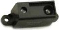
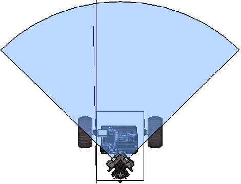
The solution to this problem is to NOT put your sensor flush with the front of your robot,
but to instead back the sensor into the robot so that the front of the robot is located
before the minimum sensor range (refer to image).
This below image is a good CAD example of this concept. Check out this forum post for more info.
Another issue is the narrowness of the IR beam. In reading sharp details and getting high accuracy, a thin beam is ideal. But the problem with a thin beam is that if it is not pointed exactly at the object, the object is therefore invisible. A common joke in robotics is that a chair is the arch-rival of a small robot. Why? Because chair legs are really thin and easy to miss by a sensor.
In contrast to the IR Range Finder would be the sonar. Sonar has really poor accuracy, but since it has a wide beam it can easily detect chair legs. Unfortunately you cannot tell the size or shape of an object with a cheap hobby sonar. Sonar also has a cone shaped beam (spreading out from the point of origin) and the Sharp IR Range Finder beam is more football shaped (the widest portion in the middle being about 16 cm wide).
An issue that these range finders have in common with sonar is cross interference. This means that the signal emitted by one sensor can potentially be read by another sensor and therefore give you bad readings. However, unlike sonar which have sound signals that can bounce off of multiple walls, you just need to make sure your IR beams do not cross in parallel (the wide parts of the football shaped beam not overlapping). This makes sense because you have over redundant sensors if the two beams cross.
Techniques With the Sharp IR Range Finder
Bumper Switch
The sharp IR can be used as a quick and easy front non-contact robot bumper on your robot.
Just place two IR devices in front of your robot and cross beams as shown. Ideally you
would perfer to use rangers that have wider beams. Note: A single sonar can do this job just as well.
My Robot Examples with Sharp IR
|
The $50 Robot - With Sharp IR check it out to learn how to add Sharp IR to YOUR robot! |
|
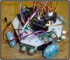
Fuzzy
3 servo scanning Sharp IR Range Finders 3 sonar as collision bumpers omni wheel speed 1 foot per second |
|
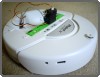
iRobot Create (modded)
1 scanning Sharp IR Range Finder high level mapping/pathfinding capabilities |
|
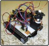
Hyper Squirrel
My very first attempt at Sharp IR rangefinders Super fast reactive 2D mapping |
Edge Detection Object Tracking
Using a sharp IR with edge detection allows for your robot to actively track
moving objects. For more information, source code, and an example, check out my
sumo robot.
This below video shows how I mount a Sharp IR to a servo:
Range Finder Basic 2D Mapping
A more advanced use for the Sharp IR Range Finder is to do mapping. To do this, you need
at least one Range Finder, and at least one non-modified servo.
The general theory is you place the range finder on the moving servo. Then have the servo rotate
to a degree, take a distance reading, and record it. Then move to the next angle, take another reading,
and then record it. Keep doing this till you have an array of distances of objects and the
corresponding angles. After your first cycle, note that your servo now must rotate back the other
direction, so you must store values into your array in reverse.
This array method can be somewhat complicated at first for several reasons. You need to understand how to store and manipulate values into an array on your microcontroller. If you do not know how to do this, look up 'arrays' in your perferred programming language to understand it, then look up the syntax rules in your microcontroller manual to program it.
Now that you know how to do this, now is the next step - making sense of all this data. First there are several things you need to understand. This array contains numbers, which corresponds to distances, which correspond to adjacent angles.
For example, a box in front of your robot might appear like this:
0 0 0 0 0 106 120 124 121 109 0 0 0 0 0
The 0's mean the beam goes on to infinity, and the numbers represent some distance. You should already know the angle between each reading (because you programmed the servo to go to that angle, duh). You should also already have a lookup table or an equation to know what distance each of the numbers equate to. So doing simple highschool geometry, because you know the distance and the angles, you can mathematically determine the width of this box. Neat, huh? You can also easily determine what angle to turn your robot to avoid this box - this is the same exact angle that the 0 after the 109 reading is at (or the 0 before the 106).
Now what if you get a reading like this:
108 120 206 12 0 0 0 0 0 57 103 120 111 9 0
Now if you were paying attention, you would know this reading shows that there are not one but two objects in front of your robot. One on the left, and one on the right. So here is where it gets trickier. See that space in between the two objects? Is your robot big enough to fit through? Maybe you just need to turn your robot slightly to point towards that center zero to fit through. Or if not, see that 0 on the far right? Perhaps your robot should turn and scan there to find a better opening or way around.
And one more example, now that you are getting the hang of this:
20 33 57 74 88 103 112 119 125 129 135 144 157 168 176
Don't see any 0's, eh? This reading shows that there is a wall in front of your robot. Notice how the numbers seem to increase as it goes to the right? That means your robot is facing the wall at an angle. This information is great if say you wanted your robot to do wall following, as you always know what angle you are to the wall. If there were zeros in your reading, that could perhaps mean your robot is looking down the hallway, or perhaps into a doorway. Calculating the angle to the wall would easily give you that information.
This is a 3D scanning and mapping test for my ERP. Its basically mapping obstacles, then choosing the most free path. It scans in only 30 points, so its fairly poor resolution. It's only the first step for a more advanced algorithm in the future.
Timing Techniques with Basic 2D Mapping
There are several timing issues which you must pay attention to when doing 2D mapping.
Be aware that your servo takes time to rotate to a certain angle, be aware that there is a small
time delay between when your sensor takes a reading and then sends this reading to
your microcontroller, and be aware that your robot is probably moving while taking these
readings. If you don't take these factors into account, your robot will undoubtably take
error and possibly crash. Make sure you check datasheets of your servo and sensor to know
this delay. A common method to bypass this delay is to tell your robot to stop moving while
scanning. But a stop and start robot is lame, you can do better. Would you look cool if you
couldn't walk with your eyes open? Exactly.
If you have made a robot that can map 2D, you will probably have realized by now that a servo rotates fairly slow (relatively speaking). And if you have a crazy fast robot (such as my Hyper Squirrel robot) you need to do mapping fast enough to keep up with those speeds. Solution? Multiple range finders! Yes, two range finders on a single servo, each rotated at an angle to each other, can let your robot map twice as fast! This is because your servo only needs to rotate half the distance now. Note that storing distance values into your array gets slightly trickier, but not by much.
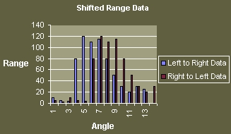
Servo reversing, where your servo returns back to the original position, should not be discounted. Your robot should record data values when your servo goes from 0 to 180 degrees, and it should record data values in reverse as it goes from 180 to 0 degrees. This effectively doubles your mapping speed. This is also a perfect way to test timing errors. If you did not take timing into account properly, you will notice a slight shift in the objects in front of your robot as your servo switches rotation directions - even when your robot is perfectly still (refer to above image)! This probably means you did not allow a pause of a few milliseconds when you told your servo to go to a new position, and then another pause of a few more milliseconds before you got your reading from the Sharp IR Range Finder. Again, the exact pause time depends on the particular servo and range finder you are using.
Sharp IR Noise
The sharp IR is actually a very noisy sensor. When I get more time, I put a nice writeup here on it.
For now, check out this forum post
and the best solution to date for it.
Advanced 2D Mapping
Want your robot to remember created maps and be able to return to recorded locations? What
you need to do for this is quite complicated and in fact is actually an active area of
research in robotics today. The most effective and popular method is called
SLAM, or
Simultaneous Localization And Mapping. For beginners, there is
the Wavefront Algorithm.
Click this image for an example of what robot mapping looks like:
Basically, have your robot record a 2D array (for X and Y positions) of positions as it moves at fixed distances. Then, using sensor data and geometry, have it calculate wall locations and record these walls into your array. But you then will have issues with error and drift, and you must compare to previous readings to check for accuracy. Correcting for this drift is yet another huge area of current research in robotics. Oh so complicated. Good luck!
You can also place beacons into your world and use other sensors. This is the most common method with cheaper more simple robots. But it requires a lot of early setup and pre-programmed knowledge into your robot.
This is an example video of mapping done on my modded iRobot Create that uses a Sharp IR rangefinder:
Laser Rangefinders
As a hobbyist you will never have enough money to afford a laser rangefinder. It works in a similar
way to a Sharp IR, except its much faster and retrieves significantly more data. Below is a video
of a laser rangefinder being used for a robot vehicle to follow a rode for the first DARPA Grand Challenge.
If you look closely, you can even made out the smooth road in the center, while the rough dirt on the side stands out.
* There are also binary digital range finders which have one fixed distance at which they send a signal. If all you require is an on/off switch, you do not need range data. A digital signal is easier to process by your electronics, so then a digital range finder would be the better option. Other digital rangefinders still return range data, but only when you tell them to through a signal line. Analog rangefinders continuously collect rangedata whether your robot wants it or not, wasting battery life.
Further Reading
The Sharp IR is a mysterious sensor once you get to the details. The SoR community has been investigating
ways to tweak, improve, and understand the sensor better. Here are various forum links you may be interested in:
Theory: sunlight only affects the Sharp IR when the sensor is moving
Society of Robots copyright 2005-2014